
PISCO PNEUMATIC

Push-In Fitting Type for Pneumatic Piping ●Push-in fitting for General Pneumatic Piping. ●Redesigned 17 models, realized weight saving. (PC,PCF,POC,PM,PMF,PL,PLL,PLH,PLF,PVX,PAX,PB,PD,PX,PRX,PKD,PKVD) ●Rotatable Resin Body after Installation. ●Wide Variety of Products. ●Centralized Piping. Tripletype(PKD,PKG,PKJ)andtwin tripletype(PKVD,PKVG)arecompact designedtoachievecentralizedpiping. ●Optional Selection of Clean-Room Package and Clean-wash Package. See "Find Part #" for Imperial/Inch/ Metric/NPT Push-In fitting ■ Model Designation (Example) P C 1/4 N1U ② Tube dia.(※Incasethat②indicatesthread,selectthreadsizefromtable③) ③ Thread size (※Incasethat③indicatestubedia.,selecttubedia.fromtable②) Thread size Metric thread (mm) Taper pipe thread Code M5 M6 01 02 03 04 Size M5×0.8 M6×1 R1/8 R1/4 R3/8 R1/2 Code Type Code Type Code Type Code Type C Straight OC Inner Hex. Straight L Elbow LL Long Elbow LH 45° Elbow H Single Banjo OL Hex. Holed Banjo B Branch Tee D Run Tee X Branch Y VX Tripod Elbow AX Branch Elbow A Twin Banjo RX Double Branch Y HW Double Banjo HT Triple Banjo AW Double Twin Banjo AT Triple Twin Banjo CF Female Straight MF Bulkhead Female Straight LF Female Elbow KD Triple Run Tee KVD Twin Triple Run Tee AF Link-up Twin Banjo HF Link-up Banjo U Union Straight E Union Tee V Union Elbow Y Union Y M Bulkhead Union MP Bulkhead Union P ML Bulkhead Union Elbow VU Tripod Union AU Branch Union Elbow ZA Union Cross G Unequal Union Straight EG Unequal Union Tee RG Unequal Double Y W Unequal Union Y KG Unequal Triple Tee KVG Unequal Twin Triple Tee ZB Unequal Cross ZC Reducing Cross GJ Unequal Plug-in Straight LJ Plug-in Elbow LGJ Unequal Plug-in Elbow LLGJ Unequal Plug-in Long Elbow LHJ 45° Plug-in Elbow LLJ Long Plug-in Elbow YJ Plug-in Y WJ Unequal Plug-in Y KJ Plug-in Triple Tee RJ Plug-in Double Y F Extension Screw Adaptor FF Unequal Screw Union IJ Union Stem IG Unequal Union Stem TJ PT Jack PF Cap P Plug ※ partsareredesignedmodels. ① Type Tube dia. inch size mm size Code 5/32 3/16 1/4 5/16 3/8 1/2 5/8 4 6 8 10 12 16 Size (mm) ø3.97 ø4.76 ø6.35 ø7.94 ø9.53 ø12.7 ø15.88 ø4 ø6 ø8 ø10 ø12 ø16 Tube Fitting ① Type ③ Thread size ② Tube dia. ④ Color and Packaging option ④ Color and Packaging option Code Color and Package classification Color Combination Remark Release ring(※) Fitting body No code Std. Black, White Black -C Clean-room package Light-blue,White Light-gray, Black Optional selection W Light-gray Light-gray Light-gray Optional selection W-C Light-gray + Clean-room pkg. Light-gray Light-gray Optional selection -UC Clean-wash and Clean-room pkg. Light-blue Light-gray Optional selection ※. Release-ring color is white for inch-size products. ※. Imperial sizes - Clean-room Pakage comes with black body. Ask us for the options W, W-C, -UC See "Find Part #" for Inch NPT Push-In fitting models Thread size UNF thread NPT thread Code U10U N0U N1U N2U N3U N4U Size 10-32UNF NPT1/16 NPT1/8 NPT1/4 NPT3/8 NPT1/2 ※Theunitofwrenchsizeisinch(thecodesuffixis“U”). ※ R thread is same as BSPT ※ Visit MINI for 1/8" O.D. and smaller body fittings. ■ Specifications Fluid medium Air / Water (※) Max. operating pressure Max. vacuum Operating temp. range ■ Construction (Elbow: PL) ※ . Make sure to follow the instructions below when the fluid medium is water. 1. Surge pressure must be controlled lower than max. operating pressure. 2. Tap water can be used. Consult with PISCO for using other kind of water. 3. Be sure to place Insert Ring into the tube edge when using water as a fluid medium. Warning Elastic sleeve (NBR) Taper pipe thread: Sealock-coating Metric thread: with gasket (SUS304+NBR or SPCC+NBR) ※ Clean-room package or Clean-wash package: POM gasket Tube Release ring (POM) Lock-claws (stainless steel) O-ring (NBR) Tube end Fitting body (PBT) Thread body (nickel-plated brass) Guide ring (nickel-plated brass) Detailed Safety Instructions Before using PISCO products, be sure to read “Safety Instructions” and “Common Safety Instructions for Products Listed in This Catalog” and “Common Safety Instructions for Fittings” Warning 1. When the fluid medium is water, do not use Tube Fitting Standard Series unless the operating environment meets all the described specifications in the catalog. Otherwise, it may cause damage to the products, the escape of tubes and a fluid leakage. Caution 1. To adjust the direction of the elbow fitting after fixing PML (Bulkhead Union Elbow) type, turn it in the clock-wise (right) direction. 2. Attach a rubber washer to the aluminum nut side when installing PML (Bulkhead Union Elbow) type. The bulkhead parts may be loosened or the rubber washer may deform if attaching it to the hexagonal side. Caution (Clean-room package, clean-wash package) 1. As for Push-In Fitting, the functional part where tube is inserted may slightly slide due to an internal pressure change and this may generate dusts. Avoid using the fitting in the clean room of ISO class from 1 to 5. Under the vibrating condition, check the amount of dust generated from the fitting and tubes, by using actual facilities. Caution (Clean-wash package) 1. Tube insertion into the push-in fitting with clean-wash spec. is tigher than that of standard spec. due to its oil-free specification. Make sure to insert tube up to tube end. 150psi (1.0MPa) -29.5in. Hg (-100kPa) 32 ~ 140°F (0 ~ 60°C) (no freezing) Connection: Thread ⇔ Tube Type Page Thread size Tube O.D. 4 6 8 10 12 16 5/32 3/16 1/4 5/16 3/8 1/2 5/8 PC Straight M5×0.8 ◎ ◎ ◎ ◎ ◎ M6×1 ◎ ◎ R1/8 ◎ ◎ ◎ ◎ ◎ ◎ ◎ ◎ ◎ R1/4 ◎ ◎ ◎ ◎ ◎ ◎ ◎ ◎ ◎ ◎ ◎ R3/8 ◎ ◎ ◎ ◎ ◎ ◎ ◎ ◎ ◎ ◎ R1/2 ◎ ◎ ◎ ◎ ◎ ◎ POC Inner Hex. Straight M5×0.8 ◎ ◎ M6×1 ◎ ◎ R1/8 ◎ ◎ ◎ ◎ ◎ ◎ R1/4 ◎ ◎ ◎ ◎ ◎ ◎ ◎ R3/8 ◎ ◎ ◎ ◎ ◎ ◎ R1/2 ◎ ◎ ◎ ◎ PCF Female Straight M5×0.8 ◎ ◎ Rc1/8 ◎ ◎ ◎ ◎ ◎ ◎ ◎ Rc1/4 ◎ ◎ ◎ ◎ ◎ ◎ ◎ ◎ ◎ ◎ ◎ Rc3/8 ◎ ◎ ◎ ◎ ◎ ◎ ◎ ◎ ◎ Rc1/2 ◎ ◎ ◎ PMF Bulkhead Female Straight Rc1/8 ◎ ◎ ◎ Rc1/4 ◎ ◎ ◎ ◎ ◎ Rc3/8 ◎ ◎ ◎ ◎ ◎ Rc1/2 ◎ ◎ PL Elbow M5×0.8 ◎ ◎ ◎ ◎ ◎ M6×1 ◎ ◎ R1/8 ◎ ◎ ◎ ◎ ◎ ◎ ◎ ◎ ◎ R1/4 ◎ ◎ ◎ ◎ ◎ ◎ ◎ ◎ ◎ ◎ ◎ R3/8 ◎ ◎ ◎ ◎ ● ◎ ◎ ◎ ◎ ● R1/2 ◎ ◎ ● ◎ ◎ ● PLL Long Elbow M5×0.8 ◎ ◎ R1/8 ◎ ◎ ◎ ◎ ◎ ◎ ◎ ◎ ◎ R1/4 ◎ ◎ ◎ ◎ ◎ ◎ ◎ ◎ ◎ ◎ ◎ R3/8 ◎ ◎ ◎ ◎ ● ◎ ◎ ◎ ◎ R1/2 ◎ ◎ ● ◎ ◎ PLH 45°Elbow R1/8 ◎ ◎ R1/4 ◎ ◎ ◎ R3/8 ◎ ◎ ◎ ● R1/2 ◎ ◎ ● POL Hex. Holed Banjo M5×0.8 ● R1/8 ● ● R1/4 ● ● ● R3/8 ● ● ● R1/2 ● PLF Female Elbow M5×0.8 ◎ ◎ ◎ ◎ ◎ M6×1 ◎ ◎ Rc1/8 ◎ ◎ ◎ ◎ ◎ ◎ ◎ Rc1/4 ◎ ◎ ◎ ◎ ◎ ◎ ◎ ◎ ◎ ◎ ◎ Rc3/8 ◎ ◎ ◎ ◎ ◎ ◎ ◎ ◎ ◎ Rc1/2 ◎ ◎ ◎ ◎ PAX Branch Elbow M5×0.8 ◎ ◎ PVX Tripod Elbow M6×1 ◎ ◎ R1/8 ◎ ◎ ◎ ◎ R1/4 ◎ ◎ ◎ ◎ ◎ R3/8 ◎ ◎ ◎ ◎ R1/2 ◎ ◎ Type Page Thread size Tube O.D. 4 6 8 10 12 16 5/32 3/16 1/4 5/16 3/8 1/2 5/8 PH Single Banjo M5×0.8 ● ● ● ● ● M6×1 ● ● R1/8 ● ● ● ● ● ● ● R1/4 ● ● ● ● ● ● ● R3/8 ● ● ● ● ● ● ● R1/2 ● ● ● PHW Double Banjo R1/8 ● ● ● ● PHT Triple Banjo R1/4 ● ● ● ● ● ● ● ● R3/8 ● ● ● ● ● ● ● ● R1/2 ● ● ● ● ● PA Twin Banjo M5×0.8 ● R1/8 ● R1/4 ● R3/8 ● R1/2 ● PAW Double Twin Banjo R1/8 ● ● ● ● PAT Triple Twin Banjo R1/4 ● ● ● ● ● ● ● ● R3/8 ● ● ● ● ● ● ● ● R1/2 ● ● ● ● ● PB Branch Tee M5×0.8 ◎ ◎ PD Run Tee M6×1 ◎ ◎ R1/8 ◎ ◎ ◎ ◎ ◎ ◎ ◎ ◎ ◎ R1/4 ◎ ◎ ◎ ◎ ◎ ◎ ◎ ◎ ◎ ◎ ◎ R3/8 ◎ ◎ ◎ ◎ ● ◎ ◎ ◎ ◎ R1/2 ◎ ◎ ● ◎ ◎ PX Branch Y M5×0.8 ◎ ◎ M6×1 ◎ ◎ R1/8 ◎ ◎ ◎ ◎ ◎ ◎ ◎ ◎ ◎ R1/4 ◎ ◎ ◎ ◎ ◎ ◎ ◎ ◎ ◎ ◎ ◎ R3/8 ◎ ◎ ◎ ◎ ● ◎ ◎ ◎ ◎ R1/2 ◎ ◎ ● ◎ ◎ PRX Double Branch Y R1/8 ◎ ◎ R1/4 ◎ Type Thread size Tube O.D.1 Tube O.D.2 4 6 8 PKD Triple Run Tee R1/8 ◎ 6 R1/4 ◎ ◎ 8 R3/8 ◎ 10 PKVD Twin Triple Run Tee R1/4 ◎ ◎ 8 R3/8 ◎ ◎ 8 ◎ ◎ 10 R1/2 ◎ ◎ 10 Type Page Thread size Tube dia.(mm) 4 6 8 10 PTJ PT Jack M5×0.8 ● ● R1/8 ● ● ● R1/4 ● ● R3/8 ● ● Type Page Thread size Thread size2 M5×0.8 Rc1/8 Rc1/4 Rc3/8 Rc1/2 PF Extension Screw Adaptor M5×0.8 ● ● R1/8 ● ● ● ● R1/4 ● ● ● ● ● R3/8 ● ● ● ● R1/2 ● PFF Unequal Screw Union Rc1/8 ● Rc1/4 ● Rc3/8 ● ● Rc1/2 ● ● Type Thread size Tube O.D. Thread size2 4 6 8 10 12 5/32 3/16 1/4 5/16 3/8 1/2 PHF Link-up Banjo M5×0.8 ● ● ● ● ● M5×0.8 R1/8 ● ● ● ● ● ● ● Rc1/8 R1/4 ● ● ● ● ● ● ● Rc1/4 R3/8 ● ● ● ● ● ● Rc3/8 R1/2 ● ● Rc1/2 PAF Link-up Twin Banjo M5×0.8 ● M5×0.8 R1/8 ● Rc1/8 R1/4 ● Rc1/4 R3/8 ● ● Rc3/8 R1/2 ● Rc1/2 Connection: Thread ⇔ Fitting Connection: Thread ⇔ Thread ※. “◎” marks are redesigned models. ■ Metric Size List The blow are tubing size charts available combination with R threads. Union types/Reducers/Plugs/etc. - both metric and inch sizes. See " . Find Part #" as to wide variety of Inch/NPT or Metric fittings Connection: Tube ⇔ Tube Type Tube O.D. 4 6 8 10 12 16 5/32 3/16 1/4 5/16 3/81/2 5/8 PU Union Straight ● ● ● ● ● ● ● ● ● ● ● ● ● PM Bulkhead Union ◎ ◎ ◎ ◎ ◎ ◎ ◎ ◎ ◎ ◎ ◎ ◎ PMP Bulkhead Union P ● ● ● ● ● ● ● ● ● PV Union Elbow ● ● ● ● ● ● ● ● ● ● ● ● PML Bulkhead Union Elbow ● ● ● ● ● ● ● ● ● PAU Branch Union Elbow ● ● ● ● ● ● ● ● ● ● ● PVU Tripod Union ● ● ● ● ● ● ● ● ● ● ● PE Union Tee ● ● ● ● ● ● ● ● ● ● ● ● PY Union Y ● ● ● ● ● ● ● ● ● ● ● ● PZA Union Cross ● ● ● ● ● ● ● Type Tube O.D. 1(mm) Tube O.D. 2 4 6 8 10 12 16 5/32 3/16 1/4 5/16 3/8 1/2 5/8 PG Unequal Union Straight 6 ● 8 ● ● 10 ● ● 12 ● ● ● 16 ● ● 3/16 ● 1/4 ● ● ● 5/16 ● ● 3/8 ● ● 1/2 ● ● ● 5/8 ● PEG Unequal Union Tee 4 ● 6 ● ● 8 ● ● ● 10 ● ● ● 12 ● ● ● 16 ● ● 5/32 ● ● 3/16 ● ● 1/4 ● ● ● 5/16 ● ● ● ● 3/8 ● ● ● 1/2 ● ● PW Unequal Union Y 6 ● 8 ● ● 10 ● ● 12 ● ● 16 ● 3/16 ● 1/4 ● ● ● 5/16 ● ● 3/8 ● ● 1/2 ● ● PRG Unequal Double Y 6 ● 8 ● 3/16 ● 1/4 ● 5/16 ● PKG Unequal Triple Tee 6 ● 8 ● ● 10 ● ● 3/16 ● 5/16 ● ● ● 3/8 ● ● PKVG Unequal Twin Triple Tee 8 ● ● 10 ● ● 5/16 ● ● ● 3/8 ● ● ● PZB Unequal Cross 8 ● PZC Reducing Cross 10 ● 12 ● 5/16 ● 3/8 ● 1/2 ● Type Tube dia. (mm), Tube O.D. 4 6 8 10 12 16 5/32 1/4 5/16 3/8 1/2 PLJ Plug-in Elbow ● ● ● ● ● ● ● ● ● ● ● PLLJ Long Plug-in Elbow ● ● ● ● ● ● ● ● ● ● PLHJ 45°Plug-in Elbow ● ● ● ● PYJ Plug-in Y ● ● ● ● ● ● ● ● ● ● Connection: Tube ⇔ Fitting Type Tube dia. (mm) 4 6 8 10 12 16 5/32 3/16 1/4 5/16 3/8 1/2 PIJ Union Stem ● ● ● ● ● ● ● ● ● ● ● ● Type Tube dia. 1 (mm) Tube dia. 2 (mm) 4 6 8 10 12 5/32 3/16 1/4 5/16 3/8 PIG Unequal Union Stem 6 ● 8 ● ● 10 ● ● 12 ● ● 16 ● ● 3/16 ● 1/4 ● ● 5/16 ● 3/8 ● 1/2 ● Type Tube O.D. 4 6 8 10 12 16 1/8 5/32 3/16 1/4 5/16 3/8 1/2 PPF Cap ● ● ● ● ● ● ● ● ● ● ● ● ● PP Plug ● ● ● ● ● ● ● ● ● ● ● ● Connection: Fitting ⇔ Fitting Plug Type Tube dia. (mm) Tube O.D. 4 6 8 10 12 5/32 3/16 1/4 5/16 3/8 PGJ Unequal Plug-in Straight 4 ● 6 ● ● 8 ● ● ● ● 10 ● ● ● ● ● ● 12 ● ● ● ● ● ● 16 ● ● 1/4 ● 5/16 ● ● 3/8 ● ● 1/2 ● ● ● PLGJ Unequal Plug-in Elbow 6 ● 8 ● ● 10 ● ● 12 ● ● 16 ● 1/4 ● ● ● 5/16 ● ● 3/8 ● ● 1/2 ● ● ● PLLGJ Unequal Plug-in Long Elbow 6 ● PWJ Unequal Plug-in Y 6 ● 8 ● 10 ● 12 ● 16 ● 1/4 ● 5/16 ● 3/8 ● 1/2 ● PRJ Plug-in Double Y 6 ● 8 ● PKJ Plug-in Triple Tee 6 ● 8 ● ● 10 ● ● Equal dia. ● Equal dia. ● Equal dia. ● Unequal dia. ● Unequal dia. ● Unequal dia. ※. “◎” marks are redesigned models. See "Find Part #" as to wide variety of Inch/NPT or Metric fittingsInch/NPT or Metric fittings ■ How to insert and disconnect 1. How to insert and disconnect tubes ① Tube insertion Insert a tube into Push-in fitting up to the tube end. Lock-claws bite the tube and fix it automatically, then the elastic sleeve seals around the tube. Refer to “6. Instructions for Tube Insertion” under “Common Safety Instructions for Products Listed in This Catalog”. ② Tube disconnection The tube is disconnected by pushing release-ring to release Lock-claws. Make sure to stop air supply before the tube disconnection. Hexagonal-column Innerhexagonalsocket 2. How to tighten thread ① Tightening thread There are two ways to tighten thread. Use a spanner or an impact wrench for a hexagonal-column. A hex key is for an inner hexagonal socket. Inner hexagonal type can save spaces. Refer to “Table 2: Tightening torque / Sealock color / Gasket materials” under “8. Instructions for Installing a fitting” in “Common Safety Instructions for Products Listed in This Catalog”. See "Find Part # " for Inch NPT and Metric Push-In fittings PCPC Straight unit: inch Model Tube O.D. R A B L C Hex. Orifice Weight φD (φ mm) (g) PC4-U10U 4mm No.10-32UNF 0.11 0.78 0.67 0.59 7/16 2.4 6.2 PC4-N0U 4mm 1/16-27NPT 0.31 0.83 0.67 0.59 7/16 2.4 6.5 PC4-N1U 4mm 1/8-27NPT 0.31 0.83 0.67 0.59 7/16 3 8.3 PC4-N2U 4mm 1/4-18NPT 0.43 0.89 0.66 0.59 9/16 3 17 PC6-U10U 6mm No.10-32UNF 0.11 0.86 0.75 0.67 1/2 2.4 8.7 PC6-N0U 6mm 1/16-27NPT 0.31 1.03 0.87 0.67 1/2 2.4 11 PC6-N1U 6mm 1/8-27NPT 0.31 0.88 0.71 0.67 1/2 5 8.8 PC6-N2U 6mm 1/4-18NPT 0.43 0.93 0.70 0.67 9/16 5 15 PC6-N3U 6mm 3/8-18NPT 0.47 0.96 0.72 0.67 11/16 5.3 30 PC8-N1U 8mm 1/8-27NPT 0.31 1.10 0.94 0.72 9/16 6 14 PC8-N2U 8mm 1/4-18NPT 0.43 1.05 0.82 0.72 9/16 7 15 PC8-N3U 8mm 3/8-18NPT 0.47 1.00 0.76 0.72 11/16 7 26 PC10-N1U 10mm 1/8-27NPT 0.31 1.19 1.03 0.81 11/16 6 23 PC10-N2U 10mm 1/4-18NPT 0.43 1.17 0.94 0.81 11/16 8.5 20 PC10-N3U 10mm 3/8-18NPT 0.47 1.15 0.91 0.81 11/16 9 25 PC10-N4U 10mm 1/2-14NPT 0.59 1.20 0.88 0.81 7/8 9 48 PC12-N2U 12mm 1/4-18NPT 0.43 1.41 1.19 0.92 7/8 8.5 39 PC12-N3U 12mm 3/8-18NPT 0.47 1.26 1.02 0.92 7/8 11 32 PC12-N4U 12mm 1/2-14NPT 0.59 1.33 1.02 0.92 7/8 11 46 PC16-N3U 16mm 3/8-18NPT 0.47 1.55 1.31 0.98 1 11 61 PC16-N4U 16mm 1/2-14NPT 0.59 1.63 1.31 0.98 1 13 69 PC5/32-U10U 5/32 No.10-32UNF 0.11 0.78 0.67 0.59 7/16 2.4 6.2 PC5/32-N0U 5/32 1/16-27NPT 0.31 0.83 0.67 0.59 7/16 3 6.5 PC5/32-N1U 5/32 1/8-27NPT 0.31 0.83 0.67 0.59 7/16 3 8.3 PC5/32-N2U 5/32 1/4-18NPT 0.43 0.89 0.66 0.59 9/16 3 17 PC3/16-U10U 3/16 No.10-32UNF 0.11 0.88 0.77 0.69 1/2 2.4 9.2 PC3/16-N0U 3/16 1/16-27NPT 0.31 1.05 0.89 0.69 1/2 3 12 PC3/16-N1U 3/16 1/8-27NPT 0.31 0.89 0.73 0.69 1/2 4 10 PC3/16-N2U 3/16 1/4-18NPT 0.43 0.95 0.72 0.69 9/16 4 16 PC3/16-N3U 3/16 3/8-18NPT 0.47 0.98 0.74 0.69 11/16 4 30 PC1/4-U10U 1/4 No.10-32UNF 0.11 0.86 0.75 0.67 1/2 2.4 8.6 PC1/4-N0U 1/4 1/16-27NPT 0.31 1.03 0.87 0.67 1/2 3 11 PC1/4-N1U 1/4 1/8-27NPT 0.31 0.88 0.71 0.67 1/2 5.3 8.6 PC1/4-N2U 1/4 1/4-18NPT 0.43 0.93 0.70 0.67 9/16 5.3 15 PC1/4-N3U 1/4 3/8-18NPT 0.47 0.96 0.72 0.67 11/16 5.3 29 PC5/16-N1U 5/16 1/8-27NPT 0.31 1.10 0.94 0.72 9/16 6 14 PC5/16-N2U 5/16 1/4-18NPT 0.43 1.05 0.82 0.72 9/16 7 15 PC5/16-N3U 5/16 3/8-18NPT 0.47 1.00 0.76 0.72 11/16 7 26 PC3/8-N1U 3/8 1/8-27NPT 0.31 1.19 1.03 0.81 11/16 6 23 PC3/8-N2U 3/8 1/4-18NPT 0.43 1.17 0.94 0.81 11/16 8.5 20 PC3/8-N3U 3/8 3/8-18NPT 0.47 1.15 0.91 0.81 11/16 8.5 26 PC3/8-N4U 3/8 1/2-14NPT 0.59 1.20 0.88 0.81 7/8 8.5 49 PC1/2-N2U 1/2 1/4-18NPT 0.43 1.41 1.18 0.91 7/8 8.5 38 PC1/2-N3U 1/2 3/8-18NPT 0.47 1.25 1.01 0.91 7/8 11 31 PC1/2-N4U 1/2 1/2-14NPT 0.59 1.33 1.01 0.91 7/8 11 45 PC5/8-N3U 5/8 3/8-18NPT 0.47 1.55 1.31 0.98 1 11 61 PC5/8-N4U 5/8 1/2-14NPT 0.59 1.63 1.31 0.98 1 13 69 Unified thread NPT and UNF thread compliant PC Unit:mm Model code Tube O.D. øD R A B L Tube end C Hex. H Orifice bore (ømm) Weight (g) CAD file name PC4-M5④ 4 M5×0.8 2.8 [3] 19.8 17 [16.8] 14.9 10 2.4 5.6 PC4-M5_[C] PC4-M50④ 22.7 19.9 [19.7] 8 6.1 PC4-M50_[C] PC4-M6④ M6×1 3.8 20.8 17 10 3 6 PC4-M6_[C] PC4-01④ R1/8 8 21 17 10 7.4 PC4-01_ PC4-02④ R1/4 11 22.5 16.5 14 16 PC4-02_ PC6-M5④ 6 M5×0.8 2.8 [3] 21.9 19.1 [18.9] 17 12 2.4 8.1 PC6-M5_[C] PC6-M6④ M6×1 3.8 22.9 19.1 3 8.5 PC6-M6_[C] PC6-01④ R1/8 8 22.3 18.3 5 8.2 PC6-01_ PC6-02④ R1/4 11 23.7 17.6 14 15 PC6-02_ PC6-03④ R3/8 12 24.5 18.1 17 28 PC6-03_ PC8-01④ 8 R1/8 8 27.9 23.9 18.2 14 6 14 PC8-01_ PC8-02④ R1/4 11 26.6 20.6 7 PC8-02_ PC8-03④ R3/8 12 25.5 19.2 17 25 PC8-03_ PC10-01④ 10 R1/8 8 30.3 26.3 20.7 17 6 21 PC10-01_ PC10-02④ R1/4 11 29.8 23.8 8.5 19 PC10-02_ PC10-03④ R3/8 12 29.3 23 9 24 PC10-03_ PC10-04④ R1/2 15 30.4 22.2 21 46 PC10-04_ PC12-02④ 12 R1/4 11 35.9 29.9 23.3 21 8.5 37 PC12-02_ PC12-03④ R3/8 12 31.9 25.6 11 30 PC12-03_ PC12-04④ R1/2 15 33.9 25.7 44 PC12-04_ PC16-03④ 16 R3/8 12 39.3 33 24.8 24 11 54 PC16-03_ PC16-04④ R1/2 15 41.3 33.1 13 63 PC16-04_ PC5/32-M5④ 5/32 M5×0.8 2.8 [3] 19.8 17 [16.8] 14.9 10 2.4 5.6 PC5_32-M5[_C] PC5/32-01④ R1/8 8 21 17 3 7.4 PC5_32-01_ PC5/32-02④ R1/4 11 22.5 16.5 14 16 PC5_32-02_ PC3/16-M5④ 3/16 M5×0.8 2.8 [3] 22.3 19.5 [19.3] 17.4 12 2.4 8.6 PC3_16-M5[_C] PC3/16-01④ R1/8 8 22.7 18.7 4 9 PC3_16-01_ PC3/16-02④ R1/4 11 24.1 18 14 16 PC3_16-02_ PC1/4-M5④ 1/4 M5×0.8 2.8 [3] 21.9 19.1 [18.9] 17 12 2.4 8 PC1_4-M5[_C] PC1/4-01④ R1/8 8 22.3 18.3 5.3 PC1_4-01_ PC1/4-02④ R1/4 11 23.7 17.6 14 15 PC1_4-02_ PC1/4-03④ R3/8 12 24.5 18.1 17 28 PC1_4-03_ PC5/16-01④ 5/16 R1/8 8 27.9 23.9 18.2 14 6 14 PC5_16-01_ PC5/16-02④ R1/4 11 26.6 20.6 7 PC5_16-02_ PC5/16-03④ R3/8 12 25.5 19.2 17 25 PC5_16-03_ PC3/8-01④ 3/8 R1/8 8 30.3 26.3 20.7 17 6 22 PC3_8-01_ PC3/8-02④ R1/4 11 29.8 23.8 8.5 19 PC3_8-02_ PC3/8-03④ R3/8 12 29.3 23 25 PC3_8-03_ PC3/8-04④ R1/2 15 30.4 22.2 21 47 PC3_8-04_ PC1/2-02④ 1/2 R1/4 11 35.7 29.7 23.1 21 8.5 36 PC1_2-02_ PC1/2-03④ R3/8 12 31.7 25.4 11 29 PC1_2-03_ PC1/2-04④ R1/2 15 33.7 25.5 43 PC1_2-04_ PC5/8-03④ 5/8 R3/8 12 39.3 33 24.8 24 11 54 PC5_8-03_ PC5/8-04④ R1/2 15 41.3 33.1 13 63 PC5_8-04_ ※1. ④ in Model code / Replaced with "W" for Light-gray color, "-C" for Clean-room package, "W-C" for Light-gray color and Cleanroom packge, "-UC" for Clean-wash and Clean-room package ※2. “L” is a reference value for height dimension after tightening taper thread. ※3. Dimensions in [ ] are for clean-room and clean-wash package products. ※4. Orifice bore is the smallest passage converted in terms of the diameter. PC Metric thread type PC4-M50 øD R ø9.7 B L B A L C L A C B A øD R R H H Straight compliant unit: inch Model Tube O.D. R A B L C Hex. φP Orifice Weight φD (φ mm) (g) POC4-U10U 4mm No.10-32UNF 0.11 0.78 0.67 0.59 3/32 0.38 2.5 4.6 POC4-N1U 4mm 1/8-27NPT 0.31 0.79 0.63 0.59 3/32 0.38 2.5 6.5 POC6-U10U 6mm No.10-32UNF 0.11 0.84 0.73 0.67 3/32 0.46 2.5 5.6 POC6-N1U 6mm 1/8-27NPT 0.31 0.87 0.70 0.67 5/32 0.46 4.1 7.6 POC8-N1U 8mm 1/8-27NPT 0.31 1.02 0.86 0.72 3/16 0.54 5 9 POC8-N2U 8mm 1/4-18NPT 0.43 0.99 0.76 0.72 7/32 0.54 5.8 13 POC5/32-U10U 5/32 No.10-32UNF 0.11 0.78 0.67 0.59 3/32 0.38 2.5 4.6 POC5/32-N1U 5/32 1/8-27NPT 0.31 0.79 0.63 0.59 3/32 0.38 2.5 6.5 POC3/16-U10U 3/16 No.10-32UNF 0.11 0.85 0.74 0.69 3/32 0.46 2.5 6.1 POC3/16-N1U 3/16 1/8-27NPT 0.31 0.89 0.72 0.69 1/8 0.46 3.3 8.3 POC1/4-U10U 1/4 No.10-32UNF 0.11 0.84 0.73 0.67 3/32 0.46 2.5 5.6 POC1/4-N1U 1/4 1/8-27NPT 0.31 0.87 0.70 0.67 5/32 0.46 4.1 7.4 POC1/4-N2U 1/4 1/4-18NPT 0.43 0.84 0.61 0.67 5/32 0.54 4.1 13 POC5/16-N1U 5/16 1/8-27NPT 0.31 1.02 0.86 0.72 3/16 0.54 5 9 POC5/16-N2U 5/16 1/4-18NPT 0.43 0.99 0.76 0.72 7/32 0.54 5.8 13 POC5/16-N3U 5/16 3/8-18NPT 0.47 0.87 0.63 0.72 7/32 0.66 5.8 19 POC3/8-N1U 3/8 1/8-27NPT 0.31 1.19 1.03 0.81 3/16 0.69 5 18 POC3/8-N2U 3/8 1/4-18NPT 0.43 1.17 0.94 0.81 7/32 0.69 5.8 22 POC3/8-N3U 3/8 3/8-18NPT 0.47 1.15 0.91 0.81 7/32 0.69 5.8 28 POC3/8-N4U 3/8 1/2-14NPT 0.59 1.19 0.87 0.81 7/32 0.82 5.8 45 POC1/2-N2U 1/2 1/4-18NPT 0.43 1.41 1.18 0.91 7/32 0.82 5.8 30 POC1/2-N3U 1/2 3/8-18NPT 0.47 1.25 1.01 0.91 5/16 0.82 8.3 30 POC1/2-N4U 1/2 1/2-14NPT 0.59 1.33 1.01 0.91 5/16 0.82 8.3 44 POC POC Inner Hex. Straight unified thread NPT and UNF thread compliant POC Fitting Series Metric thread type øD R øZ øP B L C A H A L B R compliant Unit:mm Model code Tube O.D. øD R A B L Tube end C Hex. H øP øZ Orifice bore (ømm) Weight (g) CAD file name POC4-M5④ 4 M5×0.8 2.8 [3] 19.7 16.9 [16.7] 14.9 2.5 9.7 9.9 2.6 4.6 POC4-M5_[C] POC4-M6④ M6×1 3.8 20.7 16.9 5.4 POC4-M6_[C] POC4-01④ R1/8 8 20 16 6.6 POC4-01_ POC6-M5④ 6 M5×0.8 2.8 [3] 21.3 18.5 [18.3] 17 2.5 11.8 11.8 2.6 5.6 POC6-M5_[C] POC6-M6④ M6×1 3.8 22.3 18.5 3 3.2 6.3 POC6-M6_[C] POC6-01④ R1/8 8 22.1 18.1 4 4.2 7.6 POC6-01_ POC6-02④ R1/4 11 21.3 15.2 13.7 13 POC6-02_ POC8-01④ 8 R1/8 8 25.9 21.9 18.2 5 13.7 13.8 5.3 8.8 POC8-01_ POC8-02④ R1/4 11 25.1 19.1 6 6.3 13 POC8-02_ POC8-03④ R3/8 12 22.2 15.9 16.8 19 POC8-03_ POC10-01④ 10 R1/8 8 30.3 26.3 20.7 5 17.5 16.8 5.3 17 POC10-01_ POC10-02④ R1/4 11 29.8 23.8 6 6.3 20 POC10-02_ POC10-03④ R3/8 12 29.3 23 26 POC10-03_ POC10-04④ R1/2 15 30.3 22.1 20.8 45 POC10-04_ POC12-02④ 12 R1/4 11 35.9 29.9 23.3 6 20.8 19.8 6.3 29 POC12-02_ POC12-03④ R3/8 12 31.9 25.6 8 8.4 31 POC12-03_ POC12-04④ R1/2 15 33.9 25.7 45 POC12-04_ POC16-03④ 16 R3/8 12 39.3 33 24.8 10 26 23 10.5 61 POC16-03_ POC16-04④ R1/2 15 40.3 32.1 12 12.6 65 POC16-04_ POC1/4-M5④ 1/4 M5×0.8 2.8 [3] 21.3 18.5 [18.3] 17 2.5 11.8 11.8 2.6 5.6 POC1_4-M5[_C] POC1/4-01④ R1/8 8 22.1 18.1 4 4.2 7.5 POC1_4-01_ POC1/4-02④ R1/4 11 21.3 15.2 13.7 12 POC1_4-02_ POC5/16-01④ 5/16 R1/8 8 25.9 21.9 18.2 5 13.7 13.8 5.3 8.8 POC5_16-01_ POC5/16-02④ R1/4 11 25.1 19.1 6 6.3 13 POC5_16-02_ POC5/16-03④ R3/8 12 22.2 15.9 16.8 19 POC5_16-03_ POC3/8-02④ 3/8 R1/4 11 29.8 23.8 20.7 6 17.5 16.8 6.3 21 POC3_8-02_ POC3/8-03④ R3/8 12 29.3 23 27 POC3_8-03_ POC3/8-04④ R1/2 15 30.3 22.1 20.8 46 POC3_8-04_ ※1. ④ in Model code / Replaced with "W" for Light-gray color, "-C" for Clean-room package, "W-C" for Light-gray color and Cleanroom packge, "-UC" for Clean-wash and Clean-room package ※2. “L” is a reference value for height dimension after tightening taper thread. ※3. Dimensions in [ ] are for clean-room and clean-wash package products. ※4. Orifice bore is the smallest passage converted in terms of the diameter. POC Inner Hex. Straight unit: inch Model Tube O.D. Rc A B E φP1 φP2 C Hex. T Orifice Weight φD (φ mm) (g) PCF4-N1U 4mm 1/8-27NPT 0.28 0.94 0.39 0.38 0.54 0.59 9/16 0.20 3 13 PCF4-N2U 4mm 1/4-18NPT 0.37 1.06 0.51 0.38 0.68 0.59 11/16 0.24 3 20 PCF6-N1U 6mm 1/8-27NPT 0.28 1.02 0.39 0.46 0.54 0.67 9/16 0.20 5 15 PCF6-N2U 6mm 1/4-18NPT 0.37 1.14 0.51 0.46 0.68 0.67 11/16 0.24 5 22 PCF8-N1U 8mm 1/8-27NPT 0.28 1.07 0.39 0.54 0.54 0.72 9/16 0.20 7 16 PCF8-N2U 8mm 1/4-18NPT 0.37 1.19 0.51 0.54 0.68 0.72 11/16 0.24 7 23 PCF10-N2U 10mm 1/4-18NPT 0.37 1.29 0.51 0.69 0.66 0.81 11/16 0.24 9 29 PCF12-N2U 12mm 1/4-18NPT 0.37 1.37 0.53 0.82 0.66 0.92 7/8 0.26 11 44 PCF12-N3U 12mm 3/8-18NPT 0.41 1.43 0.55 0.82 0.86 0.92 7/8 0.26 11 48 PCF5/32-U10U 5/32 No.10-32UNF 0.18 0.84 0.31 0.38 0.35 0.59 7/16 0.16 3 8.2 PCF5/32-N1U 5/32 1/8-27NPT 0.28 0.94 0.39 0.38 0.54 0.59 9/16 0.20 3 13 PCF5/32-N2U 5/32 1/4-18NPT 0.37 1.06 0.51 0.38 0.68 0.59 11/16 0.24 3 20 PCF3/16-U10U 3/16 No.10-32UNF 0.20 0.88 0.35 0.46 0.35 0.69 1/2 0.20 3.9 11 PCF3/16-N1U 3/16 1/8-27NPT 0.28 1.04 0.39 0.46 0.54 0.69 9/16 0.20 4 15 PCF3/16-N2U 3/16 1/4-18NPT 0.37 1.16 0.51 0.46 0.68 0.69 11/16 0.24 4 23 PCF1/4-U10U 1/4 No.10-32UNF 0.20 0.87 0.35 0.46 0.35 0.67 1/2 0.20 3.9 10 PCF1/4-N1U 1/4 1/8-27NPT 0.28 1.02 0.39 0.46 0.54 0.67 9/16 0.20 5.3 15 PCF1/4-N2U 1/4 1/4-18NPT 0.37 1.14 0.51 0.46 0.68 0.67 11/16 0.24 5.3 22 PCF1/4-N3U 1/4 3/8-18NPT 0.41 1.18 0.55 0.46 0.86 0.67 7/8 0.26 5.3 33 PCF5/16-N1U 5/16 1/8-27NPT 0.28 1.07 0.39 0.54 0.54 0.72 9/16 0.20 7 16 PCF5/16-N2U 5/16 1/4-18NPT 0.37 1.19 0.51 0.54 0.68 0.72 11/16 0.24 7 23 PCF5/16-N3U 5/16 3/8-18NPT 0.41 1.23 0.55 0.54 0.86 0.72 7/8 0.26 7 34 PCF3/8-N1U 3/8 1/8-27NPT 0.28 1.17 0.43 0.69 0.54 0.81 11/16 0.24 8.3 27 PCF3/8-N2U 3/8 1/4-18NPT 0.37 1.29 0.51 0.69 0.66 0.81 11/16 0.24 8.5 29 PCF3/8-N3U 3/8 3/8-18NPT 0.41 1.33 0.55 0.69 0.86 0.81 7/8 0.26 8.5 41 PCF1/2-N2U 1/2 1/4-18NPT 0.37 1.36 0.53 0.82 0.66 0.91 7/8 0.26 11 43 PCF1/2-N3U 1/2 3/8-18NPT 0.41 1.42 0.55 0.82 0.86 0.91 7/8 0.26 11 47 PCF1/2-N4U 1/2 1/2-14NPT 0.51 1.54 0.67 0.82 0.99 0.91 1 0.28 11 58 NPT and UNF thread Female Straight compliant PCF øD H Rc øP1 øP2 B E T C A PCF Female Straight compliant Unit:mm Model code Tube O.D. øD Rc A B E øP1 øP2 Tube end C Hex. H T Orifice bore (ømm) Weight (g) CAD file name PCF4-M5④ 4 M5×0.8 4.5 21.4 8 9.7 9 14.9 10 4 3 7.6 PCF4-M5_ PCF4-01④ Rc1/8 7 23.9 10 13.8 14 5 13 PCF4-01_ PCF4-02④ Rc1/4 9.5 26.9 13 16.8 17 6 19 PCF4-02_ PCF6-M5④ 6 M5×0.8 5 22 9 11.8 9 17 12 5 4.1 9.5 PCF6-M5_ PCF6-01④ Rc1/8 7 26 10 13.8 14 5 15 PCF6-01_ PCF6-02④ Rc1/4 9.5 29 13 16.8 17 6 21 PCF6-02_ PCF6-03④ Rc3/8 10.5 30 14 20.8 21 6.5 29 PCF6-03_ PCF8-01④ 8 Rc1/8 7 27.2 10 13.7 13.8 18.2 14 5 7 16 PCF8-01_ PCF8-02④ Rc1/4 9.5 30.2 13 16.8 17 6 22 PCF8-02_ PCF8-03④ Rc3/8 10.5 31.2 14 20.8 21 6.5 30 PCF8-03_ PCF10-02④ 10 Rc1/4 9.5 32.7 13 17.5 16.8 20.7 17 6 9 28 PCF10-02_ PCF10-03④ Rc3/8 10.5 33.7 14 20.8 21 6.5 37 PCF10-03_ PCF12-02④ 12 Rc1/4 9.5 34.8 13.5 20.8 16.8 23.3 21 6.5 11 42 PCF12-02_ PCF12-03④ Rc3/8 10.5 36.3 14 20.8 44 PCF12-03_ PCF12-04④ Rc1/2 13 39.3 17 25 24 7 54 PCF12-04_ PCF16-03④ 16 Rc3/8 10.5 37.3 15.5 26 20.8 24.8 27 8 14.2 71 PCF16-03_ PCF16-04④ Rc1/2 13 40.8 18 25 15 76 PCF16-04_ PCF5/32-01④ 5/32 Rc1/8 7 23.9 10 9.7 13.8 14.9 14 5 3 13 PCF5_32-01_ PCF5/32-02④ Rc1/4 9.5 26.9 13 16.8 17 6 19 PCF5_32-02_ PCF3/16-01④ 3/16 Rc1/8 7 26.4 10 11.8 13.8 17.4 14 5 4 16 PCF3_16-01_ PCF3/16-02④ Rc1/4 9.5 29.4 13 16.8 17 6 22 PCF3_16-02_ PCF1/4-01④ 1/4 Rc1/8 7 26 10 11.8 13.8 17 14 5 5.3 15 PCF1_4-01_ PCF1/4-02④ Rc1/4 9.5 29 13 16.8 17 6 21 PCF1_4-02_ PCF1/4-03④ Rc3/8 10.5 30 14 20.8 21 6.5 29 PCF1_4-03_ PCF5/16-01④ 5/16 Rc1/8 7 27.2 10 13.7 13.8 18.2 14 5 7 16 PCF5_16-01_ PCF5/16-02④ Rc1/4 9.5 30.2 13 16.8 17 6 22 PCF5_16-02_ PCF5/16-03④ Rc3/8 10.5 31.2 14 20.8 21 6.5 30 PCF5_16-03_ PCF3/8-02④ 3/8 Rc1/4 9.5 32.7 13 17.5 16.8 20.7 17 6 8.5 29 PCF3_8-02_ PCF3/8-03④ Rc3/8 10.5 33.7 14 20.8 21 6.5 37 PCF3_8-03_ PCF1/2-02④ 1/2 Rc1/4 9.5 34.6 13.5 20.8 16.8 23.1 21 6.5 11 41 PCF1_2-02_ PCF1/2-03④ Rc3/8 10.5 36.1 14 20.8 44 PCF1_2-03_ PCF1/2-04④ Rc1/2 13 39.1 17 25 24 7 53 PCF1_2-04_ ※1. ④ in Model code / Replaced with "W" for Light-gray color, "-C" for Clean-room package, "W-C" for Light-gray color and Cleanroom packge, "-UC" for Clean-wash and Clean-room package ※2. Orifice bore is the smallest passage converted in terms of the diameter. unit: inch Model Tube O.D. Rc M B E1 E2 A C φP Hex. H1 Hex. H2 T1 T2 Orifice Weight φD (φ mm) (g) PMF4-N1U 4mm 1/8-27NPT 1/2-20UNF 0.95 0.35 0.35 0.28 0.59 0.54 9/16 9/16 0.20 0.20 3 17 PMF6-N1U 6mm 1/8-27NPT 9/16-18UNF 1.04 0.40 0.39 0.28 0.67 0.54 11/16 11/16 0.22 0.24 5 28 PMF6-N2U 6mm 1/4-18NPT 9/16-18UNF 1.13 0.40 0.48 0.37 0.67 0.68 11/16 11/16 0.22 0.24 5 29 PMF8-N2U 8mm 1/4-18NPT 5/8-18UNF 1.18 0.39 0.51 0.37 0.72 0.66 3/4 3/4 0.22 0.24 7 33 PMF8-N3U 8mm 3/8-18NPT 5/8-18UNF 1.22 0.39 0.55 0.41 0.72 0.77 3/4 3/4 0.22 0.24 7 31 PMF10-N3U 10mm 3/8-18NPT 7/8-14UNF 1.33 0.44 0.55 0.41 0.81 0.82 1 1 0.28 0.28 9 67 PMF12-N3U 12mm 3/8-18NPT 7/8-14UNF 1.43 0.49 0.55 0.41 0.92 0.82 1 1 0.28 0.28 11 68 PMF5/32-N1U 5/32 1/8-27NPT 1/2-20UNF 0.95 0.35 0.35 0.28 0.59 0.54 9/16 9/16 0.20 0.20 3 17 PMF5/32-N2U 5/32 1/4-18NPT 1/2-20UNF 1.08 0.35 0.48 0.37 0.59 0.68 9/16 11/16 0.20 0.24 3 24 PMF3/16-N1U 3/16 1/8-27NPT 9/16-18UNF 1.06 0.40 0.39 0.28 0.69 0.54 11/16 11/16 0.22 0.24 4 28 PMF3/16-N2U 3/16 1/4-18NPT 9/16-18UNF 1.15 0.40 0.48 0.37 0.69 0.68 11/16 11/16 0.22 0.24 4 30 PMF1/4-N1U 1/4 1/8-27NPT 9/16-18UNF 1.04 0.40 0.39 0.28 0.67 0.54 11/16 11/16 0.22 0.24 5.3 28 PMF1/4-N2U 1/4 1/4-18NPT 9/16-18UNF 1.13 0.40 0.48 0.37 0.67 0.68 11/16 11/16 0.22 0.24 5.3 29 PMF1/4-N3U 1/4 3/8-18NPT 9/16-18UNF 1.20 0.40 0.55 0.41 0.67 0.77 11/16 3/4 0.22 0.24 5.3 30 PMF5/16-N1U 5/16 1/8-27NPT 5/8-18UNF 1.06 0.39 0.39 0.28 0.72 0.54 3/4 3/4 0.22 0.24 7 31 PMF5/16-N2U 5/16 1/4-18NPT 5/8-18UNF 1.18 0.39 0.51 0.37 0.72 0.66 3/4 3/4 0.22 0.24 7 33 PMF5/16-N3U 5/16 3/8-18NPT 5/8-18UNF 1.22 0.39 0.55 0.41 0.72 0.77 3/4 3/4 0.22 0.24 7 31 PMF3/8-N1U 3/8 1/8-27NPT 7/8-14UNF 1.17 0.44 0.39 0.28 0.81 0.54 1 1 0.28 0.28 8.3 66 PMF3/8-N2U 3/8 1/4-18NPT 7/8-14UNF 1.29 0.44 0.51 0.37 0.81 0.66 1 1 0.28 0.28 8.5 67 PMF3/8-N3U 3/8 3/8-18NPT 7/8-14UNF 1.33 0.44 0.55 0.41 0.81 0.82 1 1 0.28 0.28 8.5 68 PMF1/2-N2U 1/2 1/4-18NPT 7/8-14UNF 1.38 0.49 0.51 0.37 0.91 0.66 1 1 0.28 0.28 11 65 PMF1/2-N3U 1/2 3/8-18NPT 7/8-14UNF 1.42 0.49 0.55 0.41 0.91 0.82 1 1 0.28 0.28 11 66 PMF1/2-N4U 1/2 1/2-14NPT 7/8-14UNF 1.54 0.49 0.67 0.51 0.91 0.99 1 1 0.28 0.28 11 70 NPT thread compliant PMF Bulkhead Female Straight Fitting Series Unit:mm Model code Tube O.D. øD Rc M B E1 E2 A Tube end C øP Hex. H1 Hex. H2 T1 T2 Orifice bore (ømm) Weight (g) CAD file name PMF4-01④ 4 Rc1/8 M12×1 24.2 9 9 7 14.9 13.8 14 14 4 5 3 17 PMF4-01_ PMF4-02④ Rc1/4 27.5 12.3 9.5 16.8 17 6 22 PMF4-02_ PMF6-01④ 6 Rc1/8 M14×1 26.4 10.2 10 7 17 13.8 17 17 4 6 5 25 PMF6-01_ PMF6-02④ Rc1/4 28.7 12.3 9.5 16.8 26 PMF6-02_ PMF6-03④ Rc3/8 30.4 14 10.5 19.5 19 29 PMF6-03_ PMF8-01④ 8 Rc1/8 M16×1 27 9.8 10 7 18.2 13.8 19 19 4 6 7 30 PMF8-01_ PMF8-02④ Rc1/4 30 13 9.5 16.8 32 PMF8-02_ PMF8-03④ Rc3/8 31 14 10.5 19.5 30 PMF8-03_ PMF10-02④ 10 Rc1/4 M20×1 32.7 11.1 13 9.5 20.7 16.8 24 24 5 7 9 55 PMF10-02_ PMF10-03④ Rc3/8 33.7 14 10.5 20.8 56 PMF10-03_ PMF12-02④ 12 Rc1/4 M22×1 35.3 12.4 13 9.5 23.3 16.8 27 24 6 7 11 65 PMF12-02_ PMF12-03④ Rc3/8 36.3 14 10.5 20.8 PMF12-03_ PMF12-04④ Rc1/2 39.3 17 13 25 67 PMF12-04_ PMF16-03④ 16 Rc3/8 M27×1.5 38.3 14.4 14 10.5 24.8 20.8 32 29 9 8.5 14.2 110 PMF16-03_ PMF16-04④ Rc1/2 40.8 16.5 13 25 15 PMF16-04_ ※1. ④ in Model code / Replaced with "W" for Light-gray color, "-C" for Clean-room package, "W-C" for Light-gray color and Cleanroom packge, "-UC" for Clean-wash and Clean-room package ※2. Orifice bore is the smallest passage converted in terms of the diameter. øD Rc M øP B E2 E1 T1 T2 C A H2 H1 B A L1 L2 R R H øD Metric thread type B A L1 Groove for Mini type Groove for Standard type Unit:mm Model code Tube dia. øD R A B L1 L2 Hex. H Orifice bore (ømm) Weight (g) CAD file name PTJ4-M5④ 4 M5×0.8 3 [3.2] 27.5 24.5 [24.3] 18.5 8 1.8 4.1 PTJ4-M5[C] PTJ4-01④ R1/8 8 30.5 26.5 10 2.2 8.4 PTJ4-01 PTJ6-M5④ 6 M5×0.8 3 [3.2] 30.5 27.5 [27.3] 20.5 8 1.8 5.5 PTJ6-M5[C] PTJ6-01④ R1/8 8 32.5 28.5 10 4 8.7 PTJ6-01 PTJ6-02④ R1/4 11 36.5 30.5 14 19 PTJ6-02 PTJ8-01④ 8 R1/8 8 34 30 21 10 6 8.6 PTJ8-01 PTJ8-02④ R1/4 11 37 31 14 18 PTJ8-02 PTJ8-03④ R3/8 12 38.8 32.5 17 31 PTJ8-03 PTJ10-03④ 10 R3/8 12 41.5 35.2 23.5 17 8 30 PTJ10-03 ※1. ④ in Model code / Replaced with "-C" for Clean-room package, "-UC" for Clean-wash and Clean-room package. ※2. “L1” is a reference value for height dimension after tightening taper thread. ※3. PTJ withTube O.D.8mm and 10mm do not have the groove for Mini Series ※4. PTJ is applicable for PISCO Tube fitting Standard and Mini Series only. ※5. Dimensions in [ ] are for clean-room and clean-wash package products ※6. Orifice bore is the smallest passage converted in terms of the diameter. compliant PTJ PT Jack PMF Bulkhead Female Straight compliant PLPL Elbow Model Tube O.D. R A B L φP C E Hex. Orifice Weight φD (φ mm) (g) PL4-U10U 4mm No.10-32UNF 0.11 0.63 0.72 0.39 0.59 0.70 5/16 2.4 5.4 PL4-N0U 4mm 1/16-27NPT 0.31 0.87 0.90 0.39 0.59 0.74 7/16 2.8 12 PL4-N1U 4mm 1/8-27NPT 0.31 0.87 0.90 0.39 0.59 0.74 7/16 2.8 11 PL4-N2U 4mm 1/4-18NPT 0.43 1.14 1.11 0.39 0.59 0.81 9/16 2.8 18 PL6-U10U 6mm No.10-32UNF 0.11 0.77 0.91 0.49 0.67 0.80 7/16 2.4 9.1 PL6-N0U 6mm 1/16-27NPT 0.31 0.89 0.97 0.49 0.67 0.80 7/16 4.2 13 PL6-N1U 6mm 1/8-27NPT 0.31 0.89 0.97 0.49 0.67 0.80 7/16 4.2 12 PL6-N2U 6mm 1/4-18NPT 0.43 1.10 1.12 0.49 0.67 0.86 9/16 4.3 19 PL6-N3U 6mm 3/8-18NPT 0.47 1.24 1.25 0.49 0.67 0.94 11/16 4.3 31 PL8-N1U 8mm 1/8-27NPT 0.31 0.94 1.07 0.57 0.71 0.89 1/2 6 15 PL8-N2U 8mm 1/4-18NPT 0.43 1.10 1.16 0.57 0.71 0.93 9/16 6.7 20 PL8-N3U 8mm 3/8-18NPT 0.47 1.22 1.27 0.57 0.71 0.97 11/16 6.7 32 PL10-N1U 10mm 1/8-27NPT 0.31 0.98 1.17 0.69 0.80 1.00 1/2 6 19 PL10-N2U 10mm 1/4-18NPT 0.43 1.12 1.24 0.69 0.80 1.02 9/16 8 24 PL10-N3U 10mm 3/8-18NPT 0.47 1.26 1.37 0.69 0.80 1.06 11/16 8.3 36 PL10-N4U 10mm 1/2-14NPT 0.59 1.42 1.44 0.69 0.80 1.08 7/8 8.3 60 PL12-N2U 12mm 1/4-18NPT 0.43 1.17 1.36 0.83 0.92 1.14 9/16 8 27 PL12-N3U 12mm 3/8-18NPT 0.47 1.28 1.45 0.83 0.92 1.17 11/16 10 39 PL12-N4U 12mm 1/2-14NPT 0.59 1.44 1.53 0.83 0.92 1.21 7/8 10.3 63 PL16-N3U 16mm 3/8-18NPT 0.43 1.85 2.10 0.98 0.95 1.30 1 11 90 PL16-N4U 16mm 1/2-14NPT 0.59 2.01 2.18 0.98 0.95 1.30 1 13 94 PL5/32-U10U 5/32 No.10-32UNF 0.11 0.63 0.72 0.39 0.59 0.70 5/16 2.4 5.4 PL5/32-N0U 5/32 1/16-27NPT 0.31 0.87 0.90 0.39 0.59 0.74 7/16 2.8 12 PL5/32-N1U 5/32 1/8-27NPT 0.31 0.87 0.90 0.39 0.59 0.74 7/16 2.8 11 PL5/32-N2U 5/32 1/4-18NPT 0.43 1.14 1.11 0.39 0.59 0.81 9/16 2.8 18 PL3/16-U10U 3/16 No.10-32UNF 0.11 0.77 0.91 0.49 0.69 0.81 7/16 2.4 9.4 PL3/16-N0U 3/16 1/16-27NPT 0.31 0.89 0.97 0.49 0.69 0.81 7/16 3.3 14 PL3/16-N1U 3/16 1/8-27NPT 0.31 0.89 0.97 0.49 0.69 0.81 7/16 3.3 12 PL3/16-N2U 3/16 1/4-18NPT 0.43 1.10 1.12 0.49 0.69 0.87 9/16 3.3 19 PL3/16-N3U 3/16 3/8-18NPT 0.47 1.17 1.18 0.49 0.68 0.80 11/16 3.9 37 PL1/4-U10U 1/4 No.10-32UNF 0.11 0.77 0.91 0.49 0.67 0.80 7/16 2.4 9 PL1/4-N0U 1/4 1/16-27NPT 0.31 0.89 0.97 0.49 0.67 0.80 7/16 4.6 13 PL1/4-N1U 1/4 1/8-27NPT 0.31 0.89 0.97 0.49 0.67 0.80 7/16 4.6 12 PL1/4-N2U 1/4 1/4-18NPT 0.43 1.10 1.12 0.49 0.67 0.86 9/16 5.3 19 PL1/4-N3U 1/4 3/8-18NPT 0.47 1.24 1.25 0.49 0.67 0.94 11/16 5.3 31 PL5/16-N1U 5/16 1/8-27NPT 0.31 0.94 1.07 0.57 0.71 0.89 1/2 6 15 PL5/16-N2U 5/16 1/4-18NPT 0.43 1.10 1.16 0.57 0.71 0.93 9/16 6.7 20 PL5/16-N3U 5/16 3/8-18NPT 0.47 1.22 1.27 0.57 0.71 0.97 11/16 6.7 32 PL3/8-N1U 3/8 1/8-27NPT 0.31 0.98 1.17 0.69 0.80 1.00 1/2 6 19 PL3/8-N2U 3/8 1/4-18NPT 0.43 1.12 1.24 0.69 0.80 1.02 9/16 8 24 PL3/8-N3U 3/8 3/8-18NPT 0.47 1.26 1.37 0.69 0.80 1.06 11/16 8.2 36 PL3/8-N4U 3/8 1/2-14NPT 0.59 1.42 1.44 0.69 0.80 1.08 7/8 8.2 60 PL1/2-N2U 1/2 1/4-18NPT 0.43 1.17 1.36 0.83 0.93 1.15 9/16 8 26 PL1/2-N3U 1/2 3/8-18NPT 0.47 1.28 1.45 0.83 0.93 1.18 11/16 10 38 PL1/2-N4U 1/2 1/2-14NPT 0.59 1.44 1.53 0.83 0.93 1.22 7/8 10.9 63 PL5/8-N3U 5/8 3/8-18NPT 0.43 1.85 2.10 0.98 0.95 1.30 1 11 90 PL5/8-N4U 5/8 1/2-14NPT 0.59 2.01 2.18 0.98 0.95 1.30 1 13 94 unit: inch Unified thread 5/8 inch, 16mm x NPT NPT and UNF thread compliant PL Unit:mm Model code Model code R A B L øP Tube end C E Hex. H Orifice bore (ømm) Weight (g) CAD file name PL4-M5④ 4 M5×0.8 2.8 [3] 16 18.2 [18] 10 14.9 17.7 8 2.4 5.7 PL4-M5_[C] PL4-M6④ M6×1 3.8 20 21.2 18.7 10 2.8 8 PL4-M6_[C] PL4-01④ R1/8 8 22 23 2.8 10 PL4-01_ PL4-02④ R1/4 11 29 28 20.7 14 18 PL4-02_ PL6-M5④ 6 M5×0.8 2.8 [3] 19.5 23 [22.8] 12.5 17 20.3 10 2.4 8.9 PL6-M5_[C] PL6-M6④ M6×1 3.8 20.5 23 3 8 PL6-M6_[C] PL6-01④ R1/8 8 22.5 24.8 4.2 11 PL6-01_ PL6-02④ R1/4 11 28 28.2 21.8 14 4.3 19 PL6-02_ PL6-03④ R3/8 12 31.5 31.4 23.8 17 30 PL6-03_ PL8-01④ 8 R1/8 8 24 27.3 14.5 18.1 22.7 12 6 14 PL8-01_ PL8-02 ④ R1/4 11 28 29.2 23.7 14 6.7 20 PL8-02_ PL8-03 ④ R3/8 12 31 31.9 24.7 17 31 PL8-03_ PL10-01④ 10 R1/8 8 25 29.8 17.5 20.2 25.5 12 6 18 PL10-01_ PL10-02 ④ R1/4 11 28.5 31.2 26 14 8 23 PL10-02_ PL10-03 ④ R3/8 12 32 34.4 27 17 8.3 34 PL10-03_ PL10-04④ R1/2 15 36 36.6 27.5 21 57 PL10-04_ PL12-02④ 12 R1/4 11 29.8 34.2 21 23.4 29 14 8 27 PL12-02_ PL12-03④ R3/8 12 32.5 36.7 29.7 17 10 38 PL12-03_ PL12-04④ R1/2 15 36.5 38.8 30.7 21 10.3 61 PL12-04_ PL16-03④ 16 R3/8 11 47 53.2 25 24.1 33.1 22 11 74 PL16-03_ PL16-04④ R1/2 15 51 55.3 13 79 PL16-04_ øD HøP L B C E A R Metric thread type R A L B ø16mm type R øD øP C E L B A H PL Elbow compliant PL5/32-M5④ 5/32 M5×0.8 2.8 [3] 16 18.2 [18] 10 14.9 17.7 8 2.4 5.7 PL5_32-M5_[C] PL5/32-01④ R1/8 8 22 23 18.7 10 2.8 10 PL5_32-01_ PL5/32-02④ R1/4 11 29 28 20.7 14 18 PL5_32-02_ PL3/16-M5④ 3/16 M5×0.8 2.8 [3] 19.5 23 [22.8] 12.5 17.4 20.7 10 2.4 8.7 PL3_16-M5_[C] PL3/16-01④ R1/8 8 22.5 24.8 3.3 11 PL3_16-01_ PL3/16-02④ R1/4 11 28 28.2 22.2 14 19 PL3_16-02_ PL1/4-M5④ 1/4 M5×0.8 2.8 [3] 19.5 23 [22.8] 12.5 17 20.3 10 2.4 8.5 PL1_4-M5_[C] PL1/4-01④ R1/8 8 22.5 24.8 4.6 11 PL1_4-01_ PL1/4-02④ R1/4 11 28 28.2 21.8 14 5.3 18 PL1_4-02_ PL1/4-03④ R3/8 12 31.5 31.4 23.8 17 29 PL1_4-03_ PL5/16-01④ 5/16 R1/8 8 24 27.3 14.5 18.1 22.7 12 6 14 PL5_16-01_ PL5/16-02④ R1/4 11 28 29.2 23.7 14 6.7 20 PL5_16-02_ PL5/16-03④ R3/8 12 31 31.9 24.7 17 31 PL5_16-03_ PL3/8-01④ 3/8 R1/8 8 25 29.8 17.5 20.2 25.5 12 6 18 PL3_8-01_ PL3/8-02④ R1/4 11 28.5 31.2 26 14 8 24 PL3_8-02_ PL3/8-03④ R3/8 12 32 34.4 27 17 8.2 35 PL3_8-03_ PL3/8-04④ R1/2 15 36 36.6 27.5 21 58 PL3_8-04_ PL1/2-02④ 1/2 R1/4 11 29.8 34.2 21 23.7 29.3 14 8 26 PL1_2-02_ PL1/2-03④ R3/8 12 32.5 36.7 30 17 10 37 PL1_2-03_ PL1/2-04④ R1/2 15 36.5 38.8 31 21 10.9 60 PL1_2-04_ PL5/8-03④ 5/8 R3/8 11 47 53.2 25 24.1 33.1 22 11 74 PL5_8-03_ PL5/8-04④ R1/2 15 51 55.3 13 79 PL5_8-04_ ※1. ④ in Model code / Replaced with "W" for Light-gray color, "-C" for Clean-room package, "W-C" for Light-gray color and Cleanroom packge, "-UC" for Clean-wash and Clean-room package ※2. “L” is a reference value for height dimension after tightening taper thread. ※3. Dimensions in [ ] are for clean-room and clean-wash package products ※4. Orifice bore is the smallest passage converted in terms of the diameter. unit: inch Model Tube O.D. R A B L φP C E Hex. Orifice Weight φD (φ mm) (g) PLL5/32-U10U 5/32 No.10-32UNF 0.11 1.10 1.19 0.39 0.59 0.74 5/16 2.4 6.4 PLL5/32-N1U 5/32 1/8-27NPT 0.31 1.34 1.37 0.39 0.59 0.74 7/16 2.8 12 PLL5/32-N2U 5/32 1/4-18NPT 0.43 1.61 1.58 0.39 0.59 0.81 9/16 2.8 20 PLL3/16-U10U 3/16 No.10-32UNF 0.11 1.34 1.48 0.49 0.69 0.81 7/16 2.4 11 PLL3/16-N1U 3/16 1/8-27NPT 0.31 1.46 1.54 0.49 0.69 0.81 7/16 3.3 14 PLL3/16-N2U 3/16 1/4-18NPT 0.43 1.67 1.69 0.49 0.69 0.87 9/16 3.3 21 PLL3/16-N3U 3/16 3/8-18NPT 0.47 1.70 1.71 0.49 0.68 0.80 11/16 3.9 64 PLL1/4-U10U 1/4 No.10-32UNF 0.11 1.34 1.48 0.49 0.67 0.80 7/16 2.4 11 PLL1/4-N1U 1/4 1/8-27NPT 0.31 1.46 1.54 0.49 0.67 0.80 7/16 4.6 13 PLL1/4-N2U 1/4 1/4-18NPT 0.43 1.67 1.69 0.49 0.67 0.86 9/16 5.3 21 PLL1/4-N3U 1/4 3/8-18NPT 0.47 1.81 1.82 0.49 0.67 0.94 11/16 5.3 35 PLL5/16-N1U 5/16 1/8-27NPT 0.31 1.59 1.72 0.57 0.71 0.89 1/2 6 17 PLL5/16-N2U 5/16 1/4-18NPT 0.43 1.75 1.81 0.57 0.71 0.93 9/16 6.7 23 PLL5/16-N3U 5/16 3/8-18NPT 0.47 1.87 1.92 0.57 0.71 0.97 11/16 6.7 36 PLL3/8-N1U 3/8 1/8-27NPT 0.31 1.75 1.93 0.69 0.80 1.00 1/2 6 21 PLL3/8-N2U 3/8 1/4-18NPT 0.43 1.89 2.01 0.69 0.80 1.02 9/16 8 27 PLL3/8-N3U 3/8 3/8-18NPT 0.47 2.03 2.13 0.69 0.80 1.06 11/16 8.2 40 PLL3/8-N4U 3/8 1/2-14NPT 0.59 2.19 2.21 0.69 0.80 1.06 7/8 8.2 66 PLL1/2-N2U 1/2 1/4-18NPT 0.43 2.08 2.26 0.83 0.93 1.15 9/16 8 30 PLL1/2-N3U 1/2 3/8-18NPT 0.47 2.19 2.36 0.83 0.93 1.18 11/16 10 43 PLL1/2-N4U 1/2 1/2-14NPT 0.59 2.34 2.44 0.83 0.93 1.18 7/8 10.9 70 PLL PLL Long Elbow Unified thread NPT and UNF thread compliant PLL Metric thread type ø16mm type øD R H L øP B C E A A L B R H R øD øP C E L B A PLL Long Elbow compliant Unit:mm Model code Tube O.D. øD R A B L øP Tube end C E Hex. H Orifice bore (ømm) Weight (g) CAD file name PLL4-M5④ 4 M5×0.8 2.8 [3] 28 30.2 [30] 10 14.9 18.7 8 2.4 6.4 PLL4-M5_[C] PLL4-01④ R1/8 8 34 35 10 2.8 11 PLL4-01_ PLL4-02④ R1/4 11 41 40 20.7 14 19 PLL4-02_ PLL6-M5④ 6 M5×0.8 2.8 [3] 34 37.5 [37.3] 12.5 17 20.3 10 2.4 9.9 PLL6-M5_[C] PLL6-01④ R1/8 8 37 39.3 4.3 13 PLL6-01_ PLL6-02④ R1/4 11 42.5 42.7 21.8 14 20 PLL6-02_ PLL6-03④ R3/8 12 46 45.9 23.8 17 33 PLL6-03_ PLL8-01④ 8 R1/8 8 40.5 43.8 14.5 18.1 22.7 12 6 16 PLL8-01_ PLL8-02④ R1/4 11 44.5 45.7 23.7 14 6.7 22 PLL8-02_ PLL8-03④ R3/8 12 47.5 48.4 24.7 17 35 PLL8-03_ PLL10-01④ 10 R1/8 8 44.5 49.3 17.5 20.2 25.5 12 6 20 PLL10-01_ PLL10-02④ R1/4 11 48 50.7 26 14 8 26 PLL10-02_ PLL10-03④ R3/8 12 51.5 53.9 27 17 8.3 38 PLL10-03_ PLL10-04④ R1/2 15 55.5 56.1 21 63 PLL10-04_ PLL12-02④ 12 R1/4 11 52.8 57.2 21 23.4 29 14 8 30 PLL12-02_ PLL12-03④ R3/8 12 55.5 59.7 29.7 17 10 42 PLL12-03_ PLL12-04④ R1/2 15 59.5 61.8 21 10.3 68 PLL12-04_ PLL16-03④ 16 R3/8 11 74 80.2 25 24.1 33.1 22 11 154 PLL16-03_ PLL16-04④ R1/2 15 78 82.3 13 150 PLL16-04_ PLL5/32-01④ 5/32 R1/8 8 34 35 10 14.9 18.7 10 2.8 11 PLL5_32-01_ PLL5/32-02④ R1/4 11 41 40 20.7 14 19 PLL5_32-02_ PLL3/16-01④ 3/16 R1/8 8 37 39.3 12.5 17.4 20.7 10 3.3 13 PLL3_16-01_ PLL3/16-02④ R1/4 11 42.5 42.7 22.2 14 21 PLL3_16-02_ PLL1/4-01④ 1/4 R1/8 8 37 39.3 12.5 17 20.3 10 4.6 13 PLL1_4-01_ PLL1/4-02④ R1/4 11 42.5 42.7 21.8 14 5.3 20 PLL1_4-02_ PLL1/4-03④ R3/8 12 46 45.9 23.8 17 33 PLL1_4-03_ PLL5/16-01④ 5/16 R1/8 8 40.5 43.8 14.5 18.1 22.7 12 6 16 PLL5_16-01_ PLL5/16-02④ R1/4 11 44.5 45.7 23.7 14 6.7 22 PLL5_16-02_ PLL5/16-03④ R3/8 12 47.5 48.4 24.7 17 35 PLL5_16-03_ PLL3/8-01④ 3/8 R1/8 8 44.5 49.3 17.5 20.2 25.5 12 6 20 PLL3_8-01_ PLL3/8-02④ R1/4 11 48 50.7 26 14 8 27 PLL3_8-02_ PLL3/8-03④ R3/8 12 51.5 53.9 27 17 8.2 39 PLL3_8-03_ PLL3/8-04④ R1/2 15 55.5 56.1 21 63 PLL3_8-04_ PLL1/2-02④ 1/2 R1/4 11 52.8 57.2 21 23.7 29.3 14 8 30 PLL1_2-02_ PLL1/2-03④ R3/8 12 55.5 59.7 30 17 10 42 PLL1_2-03_ PLL1/2-04④ R1/2 15 59.5 61.8 21 10.9 67 PLL1_2-04_ ※1. ④ in Model code / Replaced with "W" for Light-gray color, "-C" for Clean-room package, "W-C" for Light-gray color and Cleanroom packge, "-UC" for Clean-wash and Clean-room package ※2. “L” is a reference value for height dimension after tightening taper thread. ※3. Dimensions in [ ] are for clean-room and clean-wash package products ※4. Orifice bore is the smallest passage converted in terms of the diameter. Unit:mm Model code Tube O.D. øD R A B L E F øP Tube end C Hex. H Orifice bore (ømm) Weight (g) CAD file name PLH8-01④ 8 R1/8 8 24 39.4 20.7 19.4 14.5 18.1 12 6 14 PLH8-01_ PLH8-02④ R1/4 11 28 41.4 14 6.7 20 PLH8-02_ PLH8-03④ R3/8 12 31 44 17 31 PLH8-03_ PLH10-01④ 10 R1/8 8 25 43.7 23.9 22.7 17.5 20.2 12 6 18 PLH10-01_ PLH10-02④ R1/4 11 28.5 45.2 14 8 23 PLH10-02_ PLH10-03④ R3/8 12 33 49.4 17 8.3 35 PLH10-03_ PLH10-04④ R1/2 15 37 51.6 21 58 PLH10-04_ PLH12-02④ 12 R1/4 11 29.8 51 29 27.3 21 23.4 14 8 27 PLH12-02_ PLH12-03④ R3/8 12 32.5 53.5 29.1 27.4 17 9.5 38 PLH12-03_ PLH12-04④ R1/2 15 36.5 55.7 21 10.3 61 PLH12-04_ PLH16-03④ 16 R3/8 11 43 65.6 29.8 29 25 24.1 22 11 73 PLH16-03_ PLH16-04④ R1/2 15 47 67.8 13 78 PLH16-04_ A R A R 45º 45º F F B B L L H H E C E C øD øD øP øP ø16mm type compliant PLH 45° Elbow Unit:mm Model code Tube O.D. øD R A B L1 L2 øP1 øP2 Tube end C E Hex. H Orifice bore (ømm) Weight (g) CAD file name POL4-M5④ 4 M5×0.8 3 [3.2] 17.5 14.5 [14.3] 7.5 [7.3] 10 10 14.9 19.8 4 1.8 6.3 POL4-M5[C] POL6-01④ 6 R1/8 8 24 20 11.5 13 14.3 17 23.7 5 4 15 POL6-01 POL6-02④ R1/4 11 27 21 12.5 22 POL6-02 POL8-01④ 8 R1/8 8 27 23 12 14 17.9 18.1 26.7 8 5.6 22 POL8-01 POL8-02④ R1/4 11 30 24 13 28 POL8-02 POL8-03④ R3/8 12 31 24.7 13.7 37 POL8-03 POL10-02④ 10 R1/4 11 34 28 15 18 21.3 20.7 30.7 10 7.5 40 POL10-02 POL10-03④ R3/8 12 35 28.7 15.7 49 POL10-03 POL12-03④ 12 R3/8 12 39 32.7 17.7 21 26.3 23.4 36.4 12 9.1 68 POL12-03 POL12-04④ R1/2 15 42 33.8 18.8 85 POL12-04 øP1 øD C E B L1 L2 A R H R Unified or Metric thread type B A L øP2 POL Hex. Holed Banjo compliant Ask for the dimensions of POL8-N1U POL12-N3U The dimensions of PLH8-N1U and PLH8-N2U are same as PLH5/16-N1U and PLH5/16-N2U respectively. unit: inch Model Tube O.D. R A B L E F φP C Hex. Orifice Weight φD φ(mm) (g) PLH5/16- N1U 5/16 1/8-27NPT 0.31 0.94 1.55 0.81 0.76 0.57 0.71 1/2 6.0 15 PLH5/16- N2U 5/16 1/4-18NPT 0.43 1.10 1.64 0.81 0.76 0.57 0.71 9/16 6.7 20 PLH1/4-N1U 1/4 1/8-27NPT 0.31 0.94 1.56 0.88 0.78 0.57 0.67 1/2 4.6 17 NPT thread unit: inch Model Tube O.D. R A B L1 L2 φP1 φP2 C E Hex. Orifice Weight φD φ(mm) (g) POL1/4-N1U 1/4 1/8-27NPT 0.31 0.94 0.78 0.45 0.51 0.56 0.67 0.93 3/16 4.0 16 POL1/4-N2U 1/4 1/4-18NPT 0.43 1.06 0.83 0.50 0.51 0.56 0.67 0.93 3/16 4.0 22 POL3/8-N2U 3/8 1/4-18NPT 0.43 1.34 1.11 0.60 0.71 0.84 0.81 1.21 5/16 7.5 43 NPT thread PLF PLF Female Elbow unit: inch Model Tube O.D. Rc A B L φP C E Hex. Orifice Weight φD φ(mm) (g) PLF4-N1U 4mm 1/8-27NPT 0.28 0.98 0.79 0.39 0.59 0.74 9/16 2.8 13 PLF4-N2U 4mm 1/4-18NPT 0.37 1.22 1.02 0.39 0.59 0.81 11/16 2.8 22 PLF6-N1U 6mm 1/8-27NPT 0.28 1.06 0.81 0.49 0.67 0.80 9/16 4.2 14 PLF6-N2U 6mm 1/4-18NPT 0.37 1.23 0.98 0.49 0.67 0.86 11/16 4.3 23 PLF8-N1U 8mm 1/8-27NPT 0.28 1.11 0.83 0.57 0.71 0.89 9/16 6.0 16 PLF8-N2U 8mm 1/4-18NPT 0.37 1.27 0.98 0.57 0.71 0.93 11/16 6.7 24 PLF10-N2U 10mm 1/4-18NPT 0.37 1.35 1.00 0.69 0.80 1.02 11/16 8.0 27 PLF12-N2U 12mm 1/4-18NPT 0.37 1.50 1.08 0.83 0.92 1.17 11/16 10.0 32 PLF5/32-U10U 5/32 No.10-32UNF 0.20 0.75 0.55 0.39 0.59 0.74 7/16 2.8 7.7 PLF5/32-N1U 5/32 1/8-27NPT 0.28 0.98 0.79 0.39 0.59 0.74 9/16 2.8 13 PLF5/32-N2U 5/32 1/4-18NPT 0.37 1.22 1.02 0.39 0.59 0.81 11/16 2.8 22 PLF3/16-U10U 3/16 No.10-32UNF 0.20 0.82 0.57 0.49 0.69 0.81 7/16 3.3 8.7 PLF3/16-N1U 3/16 1/8-27NPT 0.28 1.06 0.81 0.49 0.69 0.81 9/16 3.3 14 PLF3/16-N2U 3/16 1/4-18NPT 0.37 1.23 0.98 0.49 0.69 0.87 11/16 3.3 23 PLF3/16-N3U 3/16 3/8-18NPT 0.41 1.27 1.02 0.49 0.68 0.80 7/8 3.9 35 PLF1/4-U10U 1/4 No.10-32UNF 0.20 0.82 0.57 0.49 0.67 0.80 7/16 3.9 8.5 PLF1/4-N1U 1/4 1/8-27NPT 0.28 1.06 0.81 0.49 0.67 0.80 9/16 4.6 14 PLF1/4-N2U 1/4 1/4-18NPT 0.37 1.23 0.98 0.49 0.67 0.86 11/16 5.3 22 PLF1/4-N3U 1/4 3/8-18NPT 0.41 1.33 1.08 0.49 0.67 0.94 7/8 5.3 35 PLF5/16-N1U 5/16 1/8-27NPT 0.28 1.11 0.83 0.57 0.71 0.89 9/16 6.0 16 PLF5/16-N2U 5/16 1/4-18NPT 0.37 1.27 0.98 0.57 0.71 0.93 11/16 6.7 24 PLF5/16-N3U 5/16 3/8-18NPT 0.41 1.35 1.06 0.57 0.71 0.97 7/8 6.7 37 PLF3/8-N2U 3/8 1/4-18NPT 0.37 1.35 1.00 0.69 0.80 1.02 11/16 8.0 27 PLF3/8-N3U 3/8 3/8-18NPT 0.41 1.45 1.10 0.69 0.80 1.06 7/8 8.2 40 PLF3/8-N4U 3/8 1/2-14NPT 0.51 1.59 1.24 0.69 0.80 1.08 1 8.2 52 PLF1/2-N2U 1/2 1/4-18NPT 0.37 1.50 1.08 0.83 0.93 1.18 11/16 10.0 32 PLF1/2-N3U 1/2 3/8-18NPT 0.41 1.54 1.12 0.83 0.93 1.18 7/8 10.0 43 PLF1/2-N4U 1/2 1/2-14NPT 0.51 1.67 1.26 0.83 0.93 1.22 1 10.9 54 NPT and UNF thread compliant PLF Rc C E L B A HøP øD PLF Female Elbow compliant Unit:mm Model code Tube O.D. øD Rc A B L øP Tube end C E Hex. H Orifice bore (ømm) Weight (g) CAD file name PLF4-M5④ 4 M5×0.8 5 19 14 10 14.9 18.7 10 2.8 6.9 PLF4-M5_ PLF4-M6④ M6×1 6.4 PLF4-M6_ PLF4-01④ Rc1/8 7 25 20 14 14 PLF4-01_ PLF4-02④ Rc1/4 9.5 31 26 20.7 17 21 PLF4-02_ PLF6-M5④ 6 M5×0.8 5 20.8 14.5 12.5 17 20.3 10 4.1 7.8 PLF6-M5_ PLF6-M6④ M6×1 4.2 7.3 PLF6-M6_ PLF6-01④ Rc1/8 7 26.8 20.5 14 15 PLF6-01_ PLF6-02④ Rc1/4 9.5 31.3 25 21.8 17 4.3 21 PLF6-02_ PLF6-03④ Rc3/8 10.5 33.8 27.5 23.8 21 32 PLF6-03_ PLF8-01④ 8 Rc1/8 7 28.3 21 14.5 18.1 22.7 14 6.0 16 PLF8-01_ PLF8-02④ Rc1/4 9.5 32.3 25 23.7 17 6.7 23 PLF8-02_ PLF8-03④ Rc3/8 10.5 34.3 27 24.7 21 33 PLF8-03_ PLF10-02④ 10 Rc1/4 9.5 34.3 25.5 17.5 20.2 26 17 8.0 26 PLF10-02_ PLF10-03④ Rc3/8 10.5 36.8 28 27 21 8.3 36 PLF10-03_ PLF10-04④ Rc1/2 13 40.3 31.5 27.5 24 46 PLF10-04_ PLF12-02④ 12 Rc1/4 9.5 38 27.5 21 23.4 29.7 17 10.0 31 PLF12-02_ PLF12-03④ Rc3/8 10.5 39 28.5 21 40 PLF12-03_ PLF12-04④ Rc1/2 13 42.5 32 30.7 24 10.3 50 PLF12-04_ PLF5/32-M5④ 5/32 M5×0.8 5 19 14 10 14.9 18.7 10 2.8 6.9 PLF5/32-M5_ PLF5/32-01④ Rc1/8 7 25 20 14 14 PLF5/32-01_ PLF5/32-02④ Rc1/4 9.5 31 26 20.7 17 21 PLF5/32-02_ PLF3/16-M5④ 3/16 M5×0.8 5 20.8 14.5 12.5 17.4 20.7 10 3.3 8 PLF3/16-M5_ PLF3/16-01④ Rc1/8 7 26.8 20.5 14 15 PLF3/16-01_ PLF3/16-02④ Rc1/4 9.5 31.3 25 22.2 17 22 PLF3/16-02_ PLF1/4-M5④ 1/4 M5×0.8 5 20.8 14.5 12.5 17 20.3 10 4.1 7.7 PLF1/4-M5_ PLF1/4-01④ Rc1/8 7 26.8 20.5 14 4.6 15 PLF1/4-01_ PLF1/4-02④ Rc1/4 9.5 31.3 25 21.8 17 5.3 21 PLF1/4-02_ PLF1/4-03④ Rc3/8 10.5 33.8 27.5 23.8 21 31 PLF1/4-03_ PLF5/16-01④ 5/16 Rc1/8 7 28.3 21 14.5 18.1 22.7 14 6.0 16 PLF5/16-01_ PLF5/16-02④ Rc1/4 9.5 32.3 25 23.7 17 6.7 23 PLF5/16-02_ PLF5/16-03④ Rc3/8 10.5 34.3 27 24.7 21 33 PLF5/16-03_ PLF3/8-02④ 3/8 Rc1/4 9.5 34.3 25.5 17.5 20.2 26 17 8.0 26 PLF3/8-02_ PLF3/8-03④ Rc3/8 10.5 36.8 28 27 21 8.2 36 PLF3/8-03_ PLF3/8-04④ Rc1/2 13 40.3 31.5 27.5 24 46 PLF3/8-04_ PLF1/2-02④ 1/2 Rc1/4 9.5 38 27.5 21 23.7 30 17 10.0 31 PLF1/2-02_ PLF1/2-03④ Rc3/8 10.5 39 28.5 21 39 PLF1/2-03_ PLF1/2-04④ Rc1/2 13 42.5 32 31 24 10.9 54 PLF1/2-04_ ※1. ④ in Model code / Replaced with "W" for Light-gray color, "-C" for Clean-room package, "W-C" for Light-gray color and Cleanroom packge, "-UC" for Clean-wash and Clean-room package ※2. Orifice bore is the smallest passage converted in terms of the diameter. R R L B Unified or Metric thread type B A L J E A H 2-C 2-øD 2-øP compliant Unit:mm Model code Tube O.D. øD R A B L øP Tube end C J E Hex. H Orifice bore (ømm) Weight (g) CAD file name PAX4-M5④ 4 M5×0.8 2.8 [3] 20 22.2 [22] 10 14.9 10.3 18.2 10 2.4 11 PAX4-M5_[C] PAX4-M6④ M6×1 3.8 21 22.2 3 PAX4-M6_[C] PAX4-01④ R1/8 8 23 24 3.9 13 PAX4-01_ PAX4-02④ R1/4 11 27 26 19.2 14 20 PAX4-02_ PAX6-M5④ 6 M5×0.8 2.8 [3] 20.5 24 [23.8] 12.5 17 12.5 19.8 10 2.4 12 PAX6-M5_[C] PAX6-M6④ M6×1 3.8 21.5 24 3 13 PAX6-M6_[C] PAX6-01④ R1/8 8 23.5 25.8 4.2 15 PAX6-01_ PAX6-02④ R1/4 11 29 29.2 21.8 14 5.3 22 PAX6-02_ PAX6-03④ R3/8 12 31.5 31.4 23.8 17 34 PAX6-03_ PAX8-01④ 8 R1/8 8 25 28.3 14.5 18.1 14.5 22.7 12 5.7 20 PAX8-01_ PAX8-02④ R1/4 11 29 30.2 23.7 14 7.3 25 PAX8-02_ PAX8-03④ R3/8 12 32 32.9 24.7 17 37 PAX8-03_ PAX10-01④ 10 R1/8 8 25.5 30.3 17.5 20.2 17.5 25 12 6 26 PAX10-01_ PAX10-02④ R1/4 11 29.5 32.2 26 14 8 32 PAX10-02_ PAX10-03④ R3/8 12 32.5 34.9 27 17 9.2 43 PAX10-03_ PAX10-04④ R1/2 15 37 37.6 28 21 66 PAX10-04_ PAX12-02④ 12 R1/4 11 29.5 34 21 23.4 21 28.2 14 8 39 PAX12-02_ PAX12-03④ R3/8 12 33.5 37.7 29.2 17 9.7 51 PAX12-03_ PAX12-04④ R1/2 15 38 40.3 30.2 21 10.6 74 PAX12-04_ PAX Branch Elbow unit: inch Model Tube O.D. R A B L φP C J E Hex. φd F T Orifice Weight φD φ(mm) (g) PAX5/32-U10U 5/32 No.10-32UNF 0.11 0.79 0.87 0.39 0.59 0.41 0.72 7/16 - - - 2.4 11 PAX5/32-N1U 5/32 1/8-27NPT 0.31 0.91 0.94 0.39 0.59 0.41 0.72 7/16 - - - 3.9 14 PAX5/32-N2U 5/32 1/4-18NPT 0.43 1.06 1.03 0.39 0.59 0.41 0.76 9/16 - - - 3.9 21 PAX3/16-U10U 3/16 No.10-32UNF 0.11 0.81 0.94 0.49 0.69 0.49 0.80 7/16 - - - 2.4 14 PAX3/16-N1U 3/16 1/8-27NPT 0.31 0.93 1.01 0.49 0.69 0.49 0.80 7/16 - - - 4.2 16 PAX3/16-N2U 3/16 1/4-18NPT 0.43 1.14 1.16 0.49 0.69 0.49 0.87 9/16 - - - 4.6 23 PAX3/16-N3U 3/16 3/8-18NPT 0.47 1.29 1.30 0.49 0.69 0.47 1.05 11/16 0.17 0.63 0.49 3.4 42 PAX1/4-U10U 1/4 No.10-32UNF 0.11 0.81 0.94 0.49 0.67 0.49 0.78 7/16 - - - 2.4 13 PAX1/4-N1U 1/4 1/8-27NPT 0.31 0.93 1.01 0.49 0.67 0.49 0.78 7/16 - - - 4.3 16 PAX1/4-N2U 1/4 1/4-18NPT 0.43 1.14 1.16 0.49 0.67 0.49 0.86 9/16 - - - 5.9 22 PAX1/4-N3U 1/4 3/8-18NPT 0.47 1.24 1.25 0.49 0.67 0.49 0.94 11/16 - - - 5.9 35 PAX5/16-N1U 5/16 1/8-27NPT 0.31 0.98 1.11 0.57 0.71 0.57 0.89 1/2 - - - 5.7 21 PAX5/16-N2U 5/16 1/4-18NPT 0.43 1.14 1.20 0.57 0.71 0.57 0.93 9/16 - - - 7.3 25 PAX5/16-N3U 5/16 3/8-18NPT 0.47 1.26 1.31 0.57 0.71 0.57 0.97 11/16 - - - 7.3 38 PAX3/8-N1U 3/8 1/8-27NPT 0.31 1.00 1.19 0.69 0.80 0.69 0.98 1/2 - - - 6.0 26 PAX3/8-N2U 3/8 1/4-18NPT 0.43 1.16 1.28 0.69 0.80 0.69 1.02 9/16 - - - 8.0 33 PAX3/8-N3U 3/8 3/8-18NPT 0.47 1.28 1.39 0.69 0.80 0.69 1.06 11/16 - - - 9.2 45 PAX3/8-N4U 3/8 1/2-14NPT 0.59 1.46 1.48 0.69 0.80 0.69 1.10 7/8 - - - 9.2 69 PAX1/2-N2U 1/2 1/4-18NPT 0.43 1.16 1.35 0.83 0.93 0.83 1.12 9/16 - - - 8.0 38 PAX1/2-N3U 1/2 3/8-18NPT 0.47 1.32 1.49 0.83 0.93 0.83 1.16 11/16 - - - 9.8 50 PAX1/2-N4U 1/2 1/2-14NPT 0.59 1.50 1.59 0.83 0.93 0.83 1.20 7/8 - - - 10.8 75 NPT and UNF thread Unit:mm Model code Tube O.D. øD R A B L øP Tube end C E Hex. H Orifice bore (ømm) Weight (g) CAD file name PVX4-M5④ 4 M5×0.8 2.8 [3] 20.3 22.5 [22.3] 10 14.9 18.2 10 2.4 10 PVX4-M5_[C] PVX4-M6④ M6×1 3.8 21.3 22.5 3 11 PVX4-M6_[C] PVX4-01④ R1/8 8 23.3 24.3 13 PVX4-01_ PVX4-02④ R1/4 11 29 28 20.7 14 20 PVX4-02_ PVX6-M5④ 6 M5×0.8 2.8 [3] 20.3 23.7 [23.5] 12.5 17 20.5 10 2.4 12 PVX6-M5_[C] PVX6-M6④ M6×1 3.8 21.3 23.7 3 PVX6-M6_[C] PVX6-01④ R1/8 8 23.3 25.5 4.6 15 PVX6-01_ PVX6-02④ R1/4 11 28 28.2 21.8 14 22 PVX6-02_ PVX6-03④ R3/8 12 31.5 31.4 23.8 17 33 PVX6-03_ PVX8-01④ 8 R1/8 8 25 28.3 14.5 18.1 22.7 12 6 20 PVX8-01_ PVX8-02④ R1/4 11 29 30.2 23.7 14 6.7 25 PVX8-02_ PVX8-03④ R3/8 12 32 32.9 24.7 17 36 PVX8-03_ PVX10-01④ 10 R1/8 8 25.9 30.6 17.5 20.2 26 12 6 25 PVX10-01_ PVX10-02④ R1/4 11 29.4 32.1 14 8 31 PVX10-02_ PVX10-03④ R3/8 12 33 35.4 27 17 8.3 42 PVX10-03_ PVX10-04④ R1/2 15 37 37.6 27.5 21 66 PVX10-04_ PVX12-02④ 12 R1/4 11 30.8 35.2 21 23.4 30.2 14 8 37 PVX12-02_ PVX12-03④ R3/8 12 33.5 37.7 17 10 49 PVX12-03_ PVX12-04④ R1/2 15 38 40.3 31.2 21 10.3 74 PVX12-04_ R R Unified or Metric thread type B A L B L A H 2-øD 2-C 2-øP 2-E PVX Tripod Elbow compliant unit: inch Model Tube O.D. R A B L φP C E Hex. φd T F Orifice Weight φD φ(mm) (g) PVX5/32-U10U 5/32 No.10-32UNF 0.11 0.80 0.89 0.39 0.59 0.72 7/16 - - - 2.4 11 PVX5/32-N1U 5/32 1/8-27NPT 0.31 0.92 0.95 0.39 0.59 0.72 7/16 - - - 3.0 14 PVX5/32-N2U 5/32 1/4-18NPT 0.43 1.14 1.11 0.39 0.59 0.81 9/16 - - - 3.0 20 PVX3/16-U10U 3/16 No.10-32UNF 0.11 0.80 0.93 0.49 0.69 0.82 7/16 - - - 2.4 13 PVX3/16-N1U 3/16 1/8-27NPT 0.31 0.92 1.00 0.49 0.69 0.82 7/16 - - - 4.0 16 PVX3/16-N2U 3/16 1/4-18NPT 0.43 1.10 1.12 0.49 0.69 0.87 9/16 - - - 4.0 22 PVX3/16-N3U 3/16 3/8-18NPT 0.47 1.30 1.31 0.49 0.69 0.81 11/16 0.17 0.49 0.31 4.0 41 PVX1/4-U10U 1/4 No.10-32UNF 0.11 0.80 0.93 0.49 0.67 0.81 7/16 - - - 2.4 12 PVX1/4-N1U 1/4 1/8-27NPT 0.31 0.92 1.00 0.49 0.67 0.81 7/16 - - - 4.6 15 PVX1/4-N2U 1/4 1/4-18NPT 0.43 1.10 1.12 0.49 0.67 0.86 9/16 - - - 5.3 22 PVX1/4-N3U 1/4 3/8-18NPT 0.47 1.24 1.25 0.49 0.67 0.94 11/16 - - - 5.3 34 PVX5/16-N1U 5/16 1/8-27NPT 0.31 0.98 1.11 0.57 0.71 0.89 1/2 - - - 6.0 21 PVX5/16-N2U 5/16 1/4-18NPT 0.43 1.14 1.20 0.57 0.71 0.93 9/16 - - - 6.7 26 PVX5/16-N3U 5/16 3/8-18NPT 0.47 1.26 1.31 0.57 0.71 0.97 11/16 - - - 6.7 37 PVX3/8-N1U 3/8 1/8-27NPT 0.31 1.02 1.20 0.69 0.80 1.02 1/2 - - - 6.0 26 PVX3/8-N2U 3/8 1/4-18NPT 0.43 1.16 1.27 0.69 0.80 1.02 9/16 - - - 8.0 31 PVX3/8-N3U 3/8 3/8-18NPT 0.47 1.30 1.41 0.69 0.80 1.06 11/16 - - - 8.2 44 PVX3/8-N4U 3/8 1/2-14NPT 0.59 1.46 1.48 0.69 0.80 1.08 7/8 - - - 8.2 68 PVX1/2-N2U 1/2 1/4-18NPT 0.43 1.21 1.40 0.83 0.93 1.20 9/16 - - - 8.0 36 PVX1/2-N3U 1/2 3/8-18NPT 0.47 1.32 1.49 0.83 0.93 1.20 11/16 - - - 10.0 48 PVX1/2-N4U 1/2 1/2-14NPT 0.59 1.50 1.59 0.83 0.93 1.24 7/8 - - - 11.0 75 NPT and UNF thread unit: inch Model Tube O.D. R A B L 1 L 2 φP1 φP 2 C E Hex. Orifice Wt. φ φ (g) PH4-N1U 1/8-27NPT 0.31 1.06 0.90 0.47 0.39 0.61 0.59 0.87 9/16 2.8 21 PH6-N1U 6mm 1/8-27NPT 0.31 1.06 0.90 0.47 0.49 0.61 0.67 0.95 9/16 4.6 22 PH6-N2U 6mm 1/4-18NPT 0.43 1.24 1.01 0.54 0.49 0.77 0.67 1.06 11/16 4.3 37 PH8-N1U 8mm 1/8-27NPT 0.31 1.06 0.90 0.48 0.57 0.61 0.71 1.03 9/16 5.5 23 PH8-N2U 8mm 1/4-18NPT 0.43 1.24 1.01 0.54 0.57 0.77 0.71 1.11 11/16 6.0 38 PH10-N2U 10mm 1/4-18NPT 0.43 1.24 1.01 0.60 0.71 0.77 0.80 1.20 11/16 7.0 41 PH10-N3U 10mm 3/8-18NPT 0.47 1.42 1.18 0.63 0.71 0.96 0.80 1.28 7/8 8.0 65 PH12-N4U 12mm 1/2-14NPT 0.51 1.58 1.26 0.65 0.83 1.18 0.92 1.50 1 10.0 99 PH5/32-U10U 5/32 No.10-32UNF 0.12 0.68 0.56 0.24 0.39 0.39 0.59 0.83 5/16 1.8 7.3 PH5/32-N1U 5/32 1/8-27NPT 0.31 1.06 0.90 0.47 0.39 0.61 0.59 0.87 9/16 2.8 21 PH3/16-U10U 3/16 No.10-32UNF 0.12 0.68 0.56 0.29 0.49 0.39 0.69 0.93 5/16 1.8 8.3 PH3/16-N1U 3/16 1/8-27NPT 0.31 1.06 0.90 0.47 0.49 0.61 0.69 0.97 9/16 4.0 22 PH3/16-N2U 3/16 1/4-18NPT 0.43 1.24 1.01 0.54 0.49 0.77 0.69 1.07 11/16 4.0 37 PH1/4-U10U 1/4 No.10-32UNF 0.12 0.68 0.56 0.29 0.49 0.39 0.67 0.91 5/16 1.8 8.1 PH1/4-N1U 1/4 1/8-27NPT 0.31 1.06 0.90 0.47 0.49 0.61 0.67 0.95 9/16 4.6 22 PH1/4-N2U 1/4 1/4-18NPT 0.43 1.24 1.01 0.54 0.49 0.77 0.67 1.06 11/16 4.3 37 PH5/16-N1U 5/16 1/8-27NPT 0.31 1.06 0.90 0.48 0.57 0.61 0.71 1.03 9/16 5.5 23 PH5/16-N2U 5/16 1/4-18NPT 0.43 1.24 1.01 0.54 0.57 0.77 0.71 1.11 11/16 6.0 38 PH5/16-N3U 5/16 3/8-18NPT 0.47 1.42 1.18 0.63 0.57 0.96 0.71 1.19 7/8 6.0 62 PH3/8-N2U 3/8 1/4-18NPT 0.43 1.24 1.01 0.60 0.71 0.77 0.80 1.20 11/16 7.0 42 PH3/8-N3U 3/8 3/8-18NPT 0.47 1.42 1.18 0.63 0.71 0.96 0.80 1.28 7/8 8.0 65 PH1/2-N3U 1/2 3/8-18NPT 0.47 1.42 1.18 0.69 0.83 0.96 0.93 1.40 7/8 9.3 67 PH1/2-N4U 1/2 1/2-14NPT 0.51 1.58 1.26 0.65 0.83 1.18 0.93 1.52 1 10.0 99 PHPH Single Banjo Unified thread NPT and UNF thread compliant PH Fitting Series D 4mm øP1 øD C E B L1 L2 A R H R Metric thread type B A L øP2 compliant Unit:mm Model code Tube O.D. øD R A B L1 L2 øP1 øP2 Tube end C E Hex. H Orifice bore (ømm) Weight (g) CAD file name PH4-M5④ 4 M5×0.8 3 [3.2] 17.2 14.2 [14] 6.2 [6] 10 9.8 14.9 21.2 8 1.8 7.5 PH4-M5[C] PH4-M6④ M6×1 3.9 [4] 18.2 14.3 [14.2] 6.3 [6.2] 2.9 7.4 PH4-M6[C] PH4-01④ R1/8 8 27 23 12 15.4 22.2 14 2.8 21 PH4-01 PH6-M5④ 6 M5×0.8 3 [3.2] 17.2 14.2 [14] 7.4 [7.2] 12.5 9.8 17 23.1 8 1.8 8.3 PH6-M5[C] PH6-M6④ M6×1 3.9 [4] 18.2 14.3 [14.2] 7.5 [7.4] 3 PH6-M6[C] PH6-01④ R1/8 8 27 23 12 15.4 24.2 14 4.6 22 PH6-01 PH6-02④ R1/4 11 31.5 25.5 13.5 19.6 26.8 17 4.3 36 PH6-02 PH8-01④ 8 R1/8 8 27 23 12.3 14.5 15.4 18.1 26.2 14 5.5 23 PH8-01 PH8-02④ R1/4 11 31.5 25.5 13.5 19.6 28.2 17 6 38 PH8-02 PH8-03④ R3/8 12 36 29.7 15.7 24.4 30.2 21 60 PH8-03 PH10-02④ 10 R1/4 11 31.5 25.5 15 17.5 19.6 20.2 30.5 17 7.1 41 PH10-02 PH10-03④ R3/8 12 36 29.7 15.7 18 24.4 32.5 21 8 63 PH10-03 PH12-03④ 12 R3/8 12 36 29.7 17.2 21 24.4 23.4 35.2 21 9.3 66 PH12-03 PH12-04④ R1/2 13 40.2 32 16.5 30 38.2 24 10 97 PH12-04 PH16-03④ 16 R3/8 12 46.1 39.8 21.3 25 28 24.1 36.6 24 13 92 PH16-03 PH16-04④ R1/2 15 48.3 40.1 21.6 105 PH16-04 PH5/32-M5④ 5/32 M5×0.8 3 [3.2] 17.2 14.2 [14] 6.2 [6] 10 9.8 14.9 21.2 8 1.8 7.5 PH5_32-M5[C] PH5/32-01④ R1/8 8 27 23 12 15.4 22.2 14 2.8 21 PH5_32-01 PH3/16-M5④ 3/16 M5×0.8 3 [3.2] 17.2 14.2 [14] 7.4 [7.2] 12.5 9.8 17.4 23.5 8 1.8 8.4 PH3_16-M5[C] PH3/16-01④ R1/8 8 27 23 12 15.4 24.6 14 4 21 PH3_16-01 PH3/16-02④ R1/4 11 31.5 25.5 13.5 19.6 27.2 17 35 PH3_16-02 PH1/4-M5④ 1/4 M5×0.8 3 [3.2] 17.2 14.2 [14] 7.4 [7.2] 12.5 9.8 17 23.1 8 1.8 8.1 PH1_4-M5[C] PH1/4-01④ R1/8 8 27 23 12 15.4 24.2 14 4.6 22 PH1_4-01 PH1/4-02④ R1/4 11 31.5 25.5 13.5 19.6 26.8 17 4.7 36 PH1_4-02 PH5/16-01④ 5/16 R1/8 8 27 23 12.3 14.5 15.4 18.1 26.2 14 5.5 23 PH5_16-01 PH5/16-02④ R1/4 11 31.5 25.5 13.5 19.6 28.2 17 6 38 PH5_16-02 PH5/16-03④ R3/8 12 36 29.7 15.7 24.4 30.2 21 60 PH5_16-03 PH3/8-02④ 3/8 R1/4 11 31.5 25.5 15 17.5 19.6 20.2 30.5 17 7.1 41 PH3_8-02 PH3/8-03④ R3/8 12 36 29.7 15.7 18 24.4 32.5 21 8 63 PH3_8-03 PH1/2-03④ 1/2 R3/8 12 36 29.7 17.2 21 24.4 23.7 35.5 21 9.3 65 PH1_2-03 PH1/2-04④ R1/2 13 40.2 32 16.5 30 38.5 24 10 97 PH1_2-04 ※1. ④ in Model code / Replaced with "W" for Light-gray color, "-C" for Clean-room package, "W-C" for Light-gray color and Cleanroom packge, "-UC" for Clean-wash and Clean-room package ※2. “L1” and “L2” are reference values for height dimensions after tightening taper thread. ※3. Dimensions in [ ] are for clean-room and clean-wash package products. ※4. Orifice bore is the smallest passage converted in terms of the diameter. PH Single Banjo 2-C 2-E 2-øP 2-øD R H B L A ø16mm type 2-ø4.2 12 24 2-25.6 A L R øD E B L1 A2L2 A1 R R Metric thread type B A1 L øP2 H RcøP1 C PHF Link-up Banjo compliant Unit:mm 形 式 Tube O.D. øD R&Rc A1 A2 B L1 L2 øP1 øP2 Tube end C E Hex. H Orifice bore (ømm) Weight (g) CAD file name PHF4-M5④ 4 M5×0.8 2.9 [3.2] 5 20.1 17.2 [16.9] 7.2 [6.9] 9.9 9.8 14.9 19.9 8 1.5 7.9 PHF4-M5[C] PHF4-01④ R1/8 8 7 32.5 28.5 12 10 15.4 22.2 14 2.8 23 PHF4-01 PHF6-M5④ 6 M5×0.8 2.9 [3.2] 5 20.1 17.2 [16.9] 8.4 [8.1] 12.4 9.8 17 24 8 1.5 9 PHF6-M5[C] PHF6-01④ R1/8 8 7 32.5 28.5 12 12.5 15.4 24.2 14 4.6 24 PHF6-01 PHF6-02④ R1/4 11 9.5 38.5 32.5 13.5 19.6 26.8 17 4.3 38 PHF6-02 PHF8-01④ 8 R1/8 8 7 32.5 28.5 12.3 14.5 15.4 18.1 26.2 14 5.5 25 PHF8-01 PHF8-02④ R1/4 11 9.5 38.5 32.5 13.5 19.6 28.2 17 6 39 PHF8-02 PHF8-03④ R3/8 12 10.5 44.5 38.2 15.7 24.4 30.2 21 63 PHF8-03 PHF10-02④ 10 R1/4 11 9.5 38.5 32.5 15 17.5 19.6 20.2 30.5 17 7.1 42 PHF10-02 PHF10-03④ R3/8 12 10.5 44.5 38.2 15.7 18 24.4 32.5 21 8 66 PHF10-03 PHF12-03④ 12 R3/8 12 10.5 44.5 38.2 17.2 21 24.4 23.4 35.2 21 9.3 69 PHF12-03 PHF12-04④ R1/2 13 13 52.2 44 16.5 30 38.2 24 10 102 PHF12-04 PHF5/32-M5④ 5/32 M5×0.8 2.9 [3.2] 5 20.1 17.2 [16.9] 7.2 [6.9] 9.9 9.8 14.9 19.9 8 1.5 7.9 PHF5_32-M5[C] PHF5/32-01④ R1/8 8 7 32.5 28.5 12 10 15.4 22.2 14 2.8 23 PHF5_32-01 PHF3/16-M5④ 3/16 M5×0.8 2.9 [3.2] 5 20.1 17.2 [16.9] 8.4 [8.1] 12.4 9.8 17.4 24.4 8 1.5 8.9 PHF3_16-M5[C] PHF3/16-01④ R1/8 8 7 32.5 28.5 12 12.5 15.4 24.6 14 4 23 PHF3_16-01 PHF3/16-02④ R1/4 11 9.5 38.5 32.5 13.5 19.6 27.2 17 37 PHF3_16-02 PHF1/4-M5④ 1/4 M5×0.8 2.9 [3.2] 5 20.1 17.2 [16.9] 8.4 [8.1] 12.4 9.8 17 24 8 1.5 8.9 PHF1_4-M5[C] PHF1/4-01④ R1/8 8 7 32.5 28.5 12 12.5 15.4 24.2 14 4.6 24 PHF1_4-01 PHF1/4-02④ R1/4 11 9.5 38.5 32.5 13.5 19.6 26.8 17 4.7 38 PHF1_4-02 PHF5/16-01④ 5/16 R1/8 8 7 32.5 28.5 12.3 14.5 15.4 18.1 26.2 14 5.5 25 PHF5_16-01 PHF5/16-02④ R1/4 11 9.5 38.5 32.5 13.5 19.6 28.2 17 6 39 PHF5_16-02 PHF5/16-03④ R3/8 12 10.5 44.5 38.2 15.7 24.4 30.2 21 63 PHF5_16-03 PHF3/8-02④ 3/8 R1/4 11 9.5 38.5 32.5 15 17.5 19.6 20.2 30.5 17 7.1 43 PHF3_8-02 PHF3/8-03④ R3/8 12 10.5 44.5 38.2 15.7 18 24.4 32.5 21 8 66 PHF3_8-03 PHF1/2-03④ 1/2 R3/8 12 10.5 44.5 38.2 17.2 21 24.4 23.7 35.5 21 9.3 67 PHF1_2-03 PHF1/2-04④ R1/2 13 13 52.2 44 16.5 30 38.5 24 10 102 PHF1_2-04 ※1. ④ in Model code / Replaced with "W" for Light-gray color, "-C" for Clean-room package, "W-C" for Light-gray color and Cleanroom packge, "-UC" for Clean-wash and Clean-room package ※2. “L1” and “L2” are reference values for height dimensions after tightening taper thread. ※3. Dimensions in [ ] are for clean-room and clean-wash package products. ※4. Orifice bore is the smallest passage converted in terms of the diameter. 2-øD 2-øP1 2-C E B L1 A JL2 H R 2-øP2 compliant Unit:mm Model code Tube O.D. øD R A B L1 L2 J øP1 øP2 Tube end C E Hex. H Orifice bore (ømm) Weight (g) CAD file name PHW4-01④ 4 R1/8 8 41.6 37.6 15.5 13 10 15.4 14.9 22.2 14 3 26 PHW4-01 PHW4-02④ R1/4 11 44.6 38.6 16.5 32 PHW4-02 PHW4-03④ R3/8 12 46.6 40.3 18.2 17 46 PHW4-03 PHW6-01④ 6 R1/8 8 41.6 37.6 15.5 13 12.5 15.4 17 24.2 14 4.1 28 PHW6-01 PHW6-02④ R1/4 11 44.6 38.6 16.5 34 PHW6-02 PHW6-03④ R3/8 12 46.6 40.3 18.2 17 48 PHW6-03 PHW8-01④ 8 R1/8 8 46.6 42.6 17.5 15 14.5 19 18.1 27.7 17 6 44 PHW8-01 PHW8-02④ R1/4 11 49.6 43.6 18.5 47 PHW8-02 PHW8-03④ R3/8 12 50.6 44.3 19.2 54 PHW8-03 PHW8-04④ R1/2 15 55.6 47.4 22.3 22 87 PHW8-04 PHW10-02④ 10 R1/4 11 57.6 51.6 22 18 17.5 23 20.2 31.7 22 7.5 80 PHW10-02 PHW10-03④ R3/8 12 58.6 52.3 22.7 83 PHW10-03 PHW10-04④ R1/2 15 61.6 53.4 23.8 100 PHW10-04 PHW12-02④ 12 R1/4 11 67.8 61.8 26.8 21.6 21 27 23.4 36.7 27 8.5 137 PHW12-02 PHW12-03④ R3/8 12 68.8 62.5 27.5 10 139 PHW12-03 PHW12-04④ R1/2 15 71.8 63.6 28.6 148 PHW12-04 PHW1/4-01④ 1/4 R1/8 8 41.6 37.6 15.5 13 12.5 15.4 17 24.2 14 4.6 28 PHW1_4-01 PHW1/4-02④ R1/4 11 44.6 38.6 16.5 34 PHW1_4-02 PHW1/4-03④ R3/8 12 46.6 40.3 18.2 17 48 PHW1_4-03 PHW5/16-02④ 5/16 R1/4 11 49.6 43.6 18.5 15 14.5 19 18.1 27.7 17 6 47 PHW5_16-02 PHW5/16-03④ R3/8 12 50.6 44.3 19.2 54 PHW5_16-03 PHW5/16-04④ R1/2 15 55.6 47.4 22.3 22 87 PHW5_16-04 PHW3/8-02④ 3/8 R1/4 11 57.6 51.6 22 18 17.5 23 20.2 31.7 22 7.5 80 PHW3_8-02 PHW3/8-03④ R3/8 12 58.6 52.3 22.7 83 PHW3_8-03 PHW3/8-04④ R1/2 15 61.6 53.4 23.8 100 PHW3_8-04 ※1. ④ in Model code / Replaced with "W" for Light-gray color, "-C" for Clean-room package, "W-C" for Light-gray color and Cleanroom packge, "-UC" for Clean-wash and Clean-room package ※2. “L1” and “L2” are reference values for height dimensions after tightening thread. ※3. Orifice bore is the smallest passage converted in terms of the diameter. PHW Double Banjo NPT thread unit: inch Model Tube O.D . R A B L1 L2 J φP1 φP2 C E Hex. Orifice Weight φD φ(mm) (g) PHW5/32-N1U 5/32 1/8-27NPT 0.31 1.64 1.48 0.61 0.51 0.39 0.61 0.59 0.87 9/16 3.0 26 PHW5/32-N2U 5/32 1/4-18NPT 0.43 1.76 1.53 0.66 0.51 0.39 0.61 0.59 0.87 9/16 3.0 31 PHW1/4-N1U 1/4 1/8-27NPT 0.31 1.64 1.48 0.61 0.51 0.49 0.61 0.67 0.95 9/16 4.6 29 PHW1/4-N2U 1/4 1/4-18NPT 0.43 1.76 1.53 0.66 0.51 0.49 0.61 0.67 0.95 9/16 4.6 34 PHW1/4-N3U 1/4 3/8-18NPT 0.47 1.83 1.59 0.72 0.51 0.49 0.61 0.67 0.95 11/16 4.6 47 PHW5/16-N2U 5/16 1/4-18NPT 0.43 1.95 1.72 0.74 0.59 0.57 0.75 0.71 1.09 11/16 6.0 47 PHW5/16-N3U 5/16 3/8-18NPT 0.47 1.99 1.75 0.76 0.59 0.57 0.75 0.71 1.09 11/16 6.0 55 PHW5/16-N4U 5/16 1/2-14NPT 0.59 2.19 1.87 0.88 0.59 0.57 0.75 0.71 1.09 7/8 6.0 85 PHW3/8-N2U 3/8 1/4-18NPT 0.43 2.27 2.04 0.87 0.71 0.69 0.91 0.80 1.25 7/8 7.5 81 PHW3/8-N3U 3/8 3/8-18NPT 0.47 2.31 2.07 0.90 0.71 0.69 0.91 0.80 1.25 7/8 7.5 84 PHW3/8-N4U 3/8 1/2-14NPT 0.59 2.43 2.11 0.94 0.71 0.69 0.91 0.80 1.25 7/8 7.5 96 PHW1/2-N3U 1/2 3/8-18NPT 0.47 2.71 2.47 1.09 0.85 0.83 1.06 0.93 1.46 1 1/8 10.0 139 PHW1/2-N4U 1/2 1/2-14NPT 0.59 2.83 2.51 1.13 0.85 0.83 1.06 0.93 1.46 1 1/8 10.0 148 R 2-øD R ø16mm type 2-C L2 B L1 A E 12 2-25.6 24 2-ø4.2 2-øP H Unit:mm Model code Tube O.D. øD R A B L1 L2 J øP1 øP2 Tube end C E Hex. H Orifice bore (ømm) Weight (g) CAD file name PHT4-01④ 4 R1/8 8 54.7 50.7 15.5 13 10 15.4 14.9 22.2 14 3 33 PHT4-01 PHT4-02④ R1/4 11 57.7 51.7 16.5 39 PHT4-02 PHT4-03④ R3/8 12 59.7 53.4 18.2 17 52 PHT4-03 PHT6-01④ 6 R1/8 8 54.7 50.7 15.5 13 12.5 15.4 17 24.2 14 4.1 35 PHT6-01 PHT6-02④ R1/4 11 57.7 51.7 16.5 41 PHT6-02 PHT6-03④ R3/8 12 59.7 53.4 18.2 17 55 PHT6-03 PHT8-01④ 8 R1/8 8 61.7 57.7 17.5 15 14.5 19 18.1 27.7 17 6 56 PHT8-01 PHT8-02④ R1/4 11 64.7 58.7 18.5 59 PHT8-02 PHT8-03④ R3/8 12 65.7 59.4 19.2 66 PHT8-03 PHT8-04④ R1/2 15 70.7 62.5 22.3 22 99 PHT8-04 PHT10-02④ 10 R1/4 11 75.7 69.7 22 18 17.5 23 20.2 31.7 22 7.5 99 PHT10-02 PHT10-03④ R3/8 12 76.7 70.4 22.7 102 PHT10-03 PHT10-04④ R1/2 15 79.7 71.5 23.8 119 PHT10-04 PHT12-02④ 12 R1/4 11 89.5 83.5 26.8 21.6 21 27 23.4 36.7 27 8.5 169 PHT12-02 PHT12-03④ R3/8 12 90.5 84.2 27.5 10 171 PHT12-03 PHT12-04④ R1/2 15 93.5 85.3 28.6 180 PHT12-04 PHT1/4-01④ 1/4 R1/8 8 54.7 50.7 15.5 13 12.5 15.4 17 24.2 14 4.6 35 PHT1_4-01 PHT1/4-02④ R1/4 11 57.7 51.7 16.5 41 PHT1_4-02 PHT1/4-03④ R3/8 12 59.7 53.4 18.2 17 55 PHT1_4-03 PHT5/16-02④ 5/16 R1/4 11 64.7 58.7 18.5 15 14.5 19 18.1 27.7 17 6 59 PHT5_16-02 PHT5/16-03④ R3/8 12 65.7 59.4 19.2 66 PHT5_16-03 PHT5/16-04④ R1/2 15 70.7 62.5 22.3 22 99 PHT5_16-04 PHT3/8-02④ 3/8 R1/4 11 75.7 69.7 22 18 17.5 23 20.2 31.7 22 7.5 100 PHT3_8-02 PHT3/8-03④ R3/8 12 76.7 70.4 22.7 103 PHT3_8-03 PHT3/8-04④ R1/2 15 79.7 71.5 23.8 119 PHT3_8-04 ※1. ④ in Model code / Replaced with "W" for Light-gray color, "-C" for Clean-room package, "W-C" for Light-gray color and Cleanroom packge, "-UC" for Clean-wash and Clean-room package ※2. “L1” and “L2” are reference values for height dimensions after tightening thread. ※3. Orifice bore is the smallest passage converted in terms of the diameter. H R B L1 A L2 2-J 3-C E 3-øP2 3-øD 3-øP1 PHT Triple Banjo compliant unit: inch Model Tube O.D φD. R A B L 1 L2 J φP1 φP2 C E Hex. Orifice Weight φ(mm) (g) PHT5/32-N1U 5/32 1/8-27NPT 0.31 2.15 1.99 0.61 0.51 0.39 0.61 0.59 0.87 9/16 3.0 33 PHT5/32-N2U 5/32 1/4-18NPT 0.43 2.27 2.04 0.66 0.51 0.39 0.61 0.59 0.87 9/16 3.0 38 PHT1/4-N1U 1/4 1/8-27NPT 0.31 2.15 1.99 0.61 0.51 0.49 0.61 0.67 0.95 9/16 4.6 36 PHT1/4-N2U 1/4 1/4-18NPT 0.43 2.27 2.04 0.66 0.51 0.49 0.61 0.67 0.95 9/16 4.6 41 PHT1/4-N3U 1/4 3/8-18NPT 0.47 2.35 2.11 0.72 0.51 0.49 0.61 0.67 0.95 11/16 4.6 55 PHT5/16-N2U 5/16 1/4-18NPT 0.43 2.55 2.32 0.74 0.59 0.57 0.75 0.71 1.09 11/16 6.0 59 PHT5/16-N3U 5/16 3/8-18NPT 0.47 2.59 2.35 0.76 0.59 0.57 0.75 0.71 1.09 11/16 6.0 67 PHT5/16-N4U 5/16 1/2-14NPT 0.59 2.78 2.46 0.88 0.59 0.57 0.75 0.71 1.09 7/8 6.0 97 PHT3/8-N2U 3/8 1/4-18NPT 0.43 2.98 2.75 0.87 0.71 0.69 0.91 0.80 1.25 7/8 7.5 100 PHT3/8-N3U 3/8 3/8-18NPT 0.47 3.02 2.78 0.90 0.71 0.69 0.91 0.80 1.25 7/8 7.5 103 PHT3/8-N4U 3/8 1/2-14NPT 0.59 3.14 2.82 0.94 0.71 0.69 0.91 0.80 1.25 7/8 7.5 116 PHT1/2-N3U 1/2 3/8-18NPT 0.47 3.56 3.32 1.09 0.85 0.83 1.06 0.93 1.46 1 1/8 10.0 170 PHT1/2-N4U 1/2 1/2-14NPT 0.59 3.68 3.36 1.13 0.85 0.83 1.06 0.93 1.46 1 1/8 10.0 179 NPT thread Unit:mm Model code Tube O.D. øD R A B L1 L2 øP1 øP2 Tube end C J E ød F T Hex. H Orifice bore (ømm) Weight (g) CAD file name PA4-M5④ 4 M5×0.8 3 [3.2] 17.2 14.2 [14] 6.2 [6] 10 9.8 14.9 10 20.2 - - - 8 1.8 9.6 PA4-M5[C] PA6-01④ 6 R1/8 8 27 23 12 12.4 15.4 17 12 26.2 3.2 10.7 14 14 4.2 25 PA6-01 PA8-02④ 8 R1/4 11 31.5 25.5 13.5 14.4 19 18.2 14 29.4 3.2 12.5 15 17 6 42 PA8-02 PA10-03④ 10 R3/8 12 36 29.7 15.7 17.6 23 20.7 17 33.5 4.2 15 18 21 8 70 PA10-03 PA12-04④ 12 R1/2 13 40.2 32 16.5 21 27 23.4 20 37.4 4.2 17 21 24 10 106 PA12-04 2-øD 2-øP1 2-C E B L1 L2 A R H R F J T ød Unified or Metric thread type B A L øP2 compliant PA Twin Banjo Unit:mm Model code Tube O.D. øD R&Rc A1 A2 B L1 L2 øP1 øP2 Tube end C J E ød F T Hex. H Orifice bore (ømm) Weight (g) CAD file name PAF4-M5④ 4 M5×0.8 3 [3.2] 5 20.2 17.2 [17] 6.2 [6] 10 9.8 14.9 10 20.2 - - - 8 1.8 11 PAF4-M5[C] PAF6-01④ 6 R1/8 8 7 32.5 28.5 12 12.4 15.4 17 12 26.2 3.2 10.7 14 14 4.2 27 PAF6-01 PAF8-02④ 8 R1/4 11 9.5 38.5 32.5 13.5 14.4 19 18.2 14 29.4 3.2 12.5 15 17 6 44 PAF8-02 PAF10-03④ 10 R3/8 12 10.5 44.5 38.2 15.7 17.6 23 20.7 17 33.5 4.2 15 18 21 8 73 PAF10-03 PAF12-03④ 12 R3/8 12 10.5 51.2 44.9 17.4 21 27 23.4 20 37.4 4.2 17 21 24 9.3 123 PAF12-03 PAF12-04④ R1/2 13 13 52.2 44 16.5 10 111 PAF12-04 2-øD T 2-øP1 2-C E B L1 A1 R H R F J ød A2 L2 Rc Metric thread type B A1 L øP2 PAF Link-up Twin Banjo compliant Common caution in this page ※1. ④ in Model code / Replaced with "W" for Light-gray color, "-C" for Clean-room package, "W-C" for Light-gray color and Cleanroom packge, "-UC" for Clean-wash and Clean-room package ※2. “L1” and “L2” are reference values for height dimensions after tightening taper thread. ※3. Dimensions in [ ] are for clean-room and clean-wash package products. ※4. Orifice bore is the smallest passage converted in terms of the diameter. NPT thread unit: inch Model Tube O.D. R A B L1 L2 φP1 φP2 C J E φd F Hex. T Orifice Weight φD φ(mm) (g) PA5/32-U10U 5/32 No.10-32UNF 0.12 0.68 0.56 0.24 0.39 0.39 0.59 0.39 0.80 - - 5/16 - 1.8 9.5 PA3/16-N1U 3/16 1/8-27NPT 0.31 1.06 0.90 0.47 0.49 0.61 0.69 0.47 1.05 0.13 0.42 9/16 0.55 3.6 26 PA1/4-N1U 1/4 1/8-27NPT 0.31 1.06 0.90 0.47 0.49 0.61 0.67 0.47 1.03 0.13 0.42 9/16 0.55 4.2 25 PA5/16-N2U 5/16 1/4-18NPT 0.43 1.24 1.01 0.54 0.57 0.75 0.72 0.55 1.16 0.13 0.49 11/16 0.59 6.0 43 PA3/8-N3U 3/8 3/8-18NPT 0.47 1.42 1.18 0.63 0.69 0.91 0.81 0.67 1.32 0.17 0.59 7/8 0.71 8.0 72 PA1/2-N4U 1/2 1/2-14NPT 0.51 1.58 1.26 0.65 0.83 1.06 0.93 0.79 1.48 0.17 0.67 1 0.83 10.0 106 R H B L1 A J1L2 4-C E 2-øP2 J2 4-øD 4-øP1 PAW Double Twin Banjo compliant Unit:mm Model code Tube O.D. øD R A B L1 L2 J1 J2 øP1 øP2 Tube end C E Hex. H Orifice bore (ømm) Weight (g) CAD file name PAW4-01④ 4 R1/8 8 41.6 37.6 15.5 13 10 10 15.4 14.9 22.2 14 3 31 PAW4-01 PAW4-02④ R1/4 11 44.6 38.6 16.5 37 PAW4-02 PAW4-03④ R3/8 12 46.6 40.3 18.2 17 51 PAW4-03 PAW6-01④ 6 R1/8 8 41.6 37.6 15.5 13 12 12.5 15.4 17 24.2 14 3.7 35 PAW6-01 PAW6-02④ R1/4 11 44.6 38.6 16.5 40 PAW6-02 PAW6-03④ R3/8 12 46.6 40.3 18.2 17 54 PAW6-03 PAW8-01④ 8 R1/8 8 46.6 42.6 17.5 15 14 14.5 19 18.1 27.7 17 6 54 PAW8-01 PAW8-02④ R1/4 11 49.6 43.6 18.5 56 PAW8-02 PAW8-03④ R3/8 12 50.6 44.3 19.2 64 PAW8-03 PAW8-04④ R1/2 15 55.6 47.4 22.3 22 96 PAW8-04 PAW10-02④ 10 R1/4 11 57.6 51.6 22 18 17 17.5 23 20.2 31.7 22 7.5 95 PAW10-02 PAW10-03④ R3/8 12 58.6 52.3 22.7 98 PAW10-03 PAW10-04④ R1/2 15 61.6 53.4 23.8 115 PAW10-04 PAW12-02④ 12 R1/4 11 67.8 61.8 26.8 21.6 20 21 27 23.4 36.7 27 8.5 160 PAW12-02 PAW12-03④ R3/8 12 68.8 62.5 27.5 9.7 162 PAW12-03 PAW12-04④ R1/2 15 71.8 63.6 28.6 171 PAW12-04 PAW1/4-01④ 1/4 R1/8 8 41.6 37.6 15.5 13 12 12.5 15.4 17 24.2 14 4.1 34 PAW1_4-01 PAW1/4-02④ R1/4 11 44.6 38.6 16.5 40 PAW1_4-02 PAW1/4-03④ R3/8 12 46.6 40.3 18.2 17 54 PAW1_4-03 PAW5/16-02④ 5/16 R1/4 11 49.6 43.6 18.5 15 14 14.5 19 18.1 27.7 17 6 56 PAW5_16-02 PAW5/16-03④ R3/8 12 50.6 44.3 19.2 64 PAW5_16-03 PAW5/16-04④ R1/2 15 55.6 47.4 22.3 22 96 PAW5_16-04 PAW3/8-02④ 3/8 R1/4 11 57.6 51.6 22 18 17 17.5 23 20.2 31.7 22 7.5 96 PAW3_8-02 PAW3/8-03④ R3/8 12 58.6 52.3 22.7 99 PAW3_8-03 PAW3/8-04④ R1/2 15 61.6 53.4 23.8 116 PAW3_8-04 ※1. ④ in Model code / Replaced with "W" for Light-gray color, "-C" for Clean-room package, "W-C" for Light-gray color and Cleanroom packge, "-UC" for Clean-wash and Clean-room package ※2. “L1” and “L2” are reference values for height dimensions after tightening thread. ※3. Orifice bore is the smallest passage converted in terms of the diameter. unit: inch Model Tube O.D. R A B L1 L2 J1 J2 φP1 φP2 C E Hex. Orifice Weight φD φ(mm) (g) PAW5/32-N1U 5/32 1/8-27NPT 0.31 1.64 1.48 0.61 0.51 0.39 0.39 0.61 0.59 0.87 9/16 3.0 31 PAW5/32-N2U 5/32 1/4-18NPT 0.43 1.76 1.53 0.66 0.51 0.39 0.39 0.61 0.59 0.87 9/16 3.0 36 PAW1/4-N1U 1/4 1/8-27NPT 0.31 1.64 1.48 0.61 0.51 0.47 0.49 0.61 0.67 0.95 9/16 4.1 35 PAW1/4-N2U 1/4 1/4-18NPT 0.43 1.76 1.53 0.66 0.51 0.47 0.49 0.61 0.67 0.95 9/16 4.1 40 PAW1/4-N3U 1/4 3/8-18NPT 0.47 1.83 1.59 0.72 0.51 0.47 0.49 0.61 0.67 0.95 11/16 4.1 54 PAW5/16-N2U 5/16 1/4-18NPT 0.43 1.95 1.72 0.74 0.59 0.55 0.57 0.75 0.71 1.09 11/16 6.0 57 PAW5/16-N3U 5/16 3/8-18NPT 0.47 1.99 1.75 0.76 0.59 0.55 0.57 0.75 0.71 1.09 11/16 6.0 64 PAW5/16-N4U 5/16 1/2-14NPT 0.59 2.19 1.87 0.88 0.59 0.55 0.57 0.75 0.71 1.09 7/8 6.0 94 PAW3/8-N2U 3/8 1/4-18NPT 0.43 2.27 2.04 0.87 0.71 0.67 0.69 0.91 0.80 1.25 7/8 7.5 96 PAW3/8-N3U 3/8 3/8-18NPT 0.47 2.31 2.07 0.90 0.71 0.67 0.69 0.91 0.80 1.25 7/8 7.5 99 PAW3/8-N4U 3/8 1/2-14NPT 0.59 2.43 2.11 0.94 0.71 0.67 0.69 0.91 0.80 1.25 7/8 7.5 116 PAW1/2-N3U 1/2 3/8-18NPT 0.47 2.71 2.47 1.09 0.85 0.79 0.83 1.06 0.93 1.46 1 1/8 9.7 160 PAW1/2-N4U 1/2 1/2-14NPT 0.59 2.83 2.51 1.13 0.85 0.79 0.83 1.06 0.93 1.46 1 1/8 9.7 169 NPT thread Unit:mm Model code Tube O.D. øD R A B L1 L2 J1 J2 øP1 øP2 Tube end C E Hex. H Orifice bore (ømm) Weight (g) CAD file name PAT4-01④ 4 R1/8 8 54.7 50.7 15.5 13 10 10 15.4 14.9 22.2 14 3 40 PAT4-01 PAT4-02④ R1/4 11 57.7 51.7 16.5 46 PAT4-02 PAT4-03④ R3/8 12 59.7 53.4 18.2 17 60 PAT4-03 PAT6-01④ 6 R1/8 8 54.7 50.7 15.5 13 12 12.5 15.4 17 24.2 14 3.7 45 PAT6-01 PAT6-02④ R1/4 11 57.7 51.7 16.5 51 PAT6-02 PAT6-03④ R3/8 12 59.7 53.4 18.2 17 65 PAT6-03 PAT8-01④ 8 R1/8 8 61.7 57.7 17.5 15 14 14.5 19 18.1 27.7 17 6 71 PAT8-01 PAT8-02④ R1/4 11 64.7 58.7 18.5 73 PAT8-02 PAT8-03④ R3/8 12 65.7 59.4 19.2 81 PAT8-03 PAT8-04④ R1/2 15 70.7 62.5 22.3 22 113 PAT8-04 PAT10-02④ 10 R1/4 11 75.7 69.7 22 18 17 17.5 23 20.2 31.7 22 7.5 122 PAT10-02 PAT10-03④ R3/8 12 76.7 70.4 22.7 126 PAT10-03 PAT10-04④ R1/2 15 79.7 71.5 23.8 142 PAT10-04 PAT12-02④ 12 R1/4 11 89.5 83.5 26.8 21.6 20 21 27 23.4 36.7 27 8.5 203 PAT12-02 PAT12-03④ R3/8 12 90.5 84.2 27.5 9.7 205 PAT12-03 PAT12-04④ R1/2 15 93.5 85.3 28.6 214 PAT12-04 PAT1/4-01④ 1/4 R1/8 8 54.7 50.7 15.5 13 12 12.5 15.4 17 24.2 14 4.1 45 PAT1_4-01 PAT1/4-02④ R1/4 11 57.7 51.7 16.5 50 PAT1_4-02 PAT1/4-03④ R3/8 12 59.7 53.4 18.2 17 64 PAT1_4-03 PAT5/16-02④ 5/16 R1/4 11 64.7 58.7 18.5 15 14 14.5 19 18.1 27.7 17 6 73 PAT5_16-02 PAT5/16-03④ R3/8 12 65.7 59.4 19.2 81 PAT5_16-03 PAT5/16-04④ R1/2 15 70.7 62.5 22.3 22 113 PAT5_16-04 PAT3/8-02④ 3/8 R1/4 11 75.7 69.7 22 18 17 17.5 23 20.2 31.7 22 7.5 124 PAT3_8-02 PAT3/8-03④ R3/8 12 76.7 70.4 22.7 125 PAT3_8-03 PAT3/8-04④ R1/2 15 79.7 71.5 23.8 143 PAT3_8-04 ※1. ④ in Model code / Replaced with "W" for Light-gray color, "-C" for Clean-room package, "W-C" for Light-gray color and Cleanroom packge, "-UC" for Clean-wash and Clean-room package ※2. “L1” and “L2” are reference values for height dimensions after tightening thread. ※3. Orifice bore is the smallest passage converted in terms of the diameter. R H B L1 A L2 2-J1 6-C E 3-øP2 J2 6-øD 6-øP1 compliant PAT Triple Twin Banjo unit: inch Model Tube O.D φD. R A B L1 L2 J1 J2 φP1 φP2 C E Hex. Orifice Weight φ(mm) (g) PAT5/32-N1U 5/32 1/8-27NPT 0.31 2.15 1.99 0.61 0.51 0.39 0.39 0.61 0.59 0.87 9/16 3.0 40 PAT5/32-N2U 5/32 1/4-18NPT 0.43 2.27 2.04 0.66 0.51 0.39 0.39 0.61 0.59 0.87 9/16 3.0 46 PAT1/4-N1U 1/4 1/8-27NPT 0.31 2.15 1.99 0.61 0.51 0.47 0.49 0.61 0.67 0.95 9/16 4.1 46 PAT1/4-N2U 1/4 1/4-18NPT 0.43 2.27 2.04 0.66 0.51 0.47 0.49 0.61 0.67 0.95 9/16 4.1 51 PAT1/4-N3U 1/4 3/8-18NPT 0.47 2.35 2.11 0.72 0.51 0.47 0.49 0.61 0.67 0.95 11/16 4.1 64 PAT5/16-N2U 5/16 1/4-18NPT 0.43 2.55 2.32 0.74 0.59 0.55 0.57 0.75 0.71 1.09 11/16 6.0 73 PAT5/16-N3U 5/16 3/8-18NPT 0.47 2.59 2.35 0.76 0.59 0.55 0.57 0.75 0.71 1.09 11/16 6.0 81 PAT5/16-N4U 5/16 1/2-14NPT 0.59 2.78 2.46 0.88 0.59 0.55 0.57 0.75 0.71 1.09 7/8 6.0 111 PAT3/8-N2U 3/8 1/4-18NPT 0.43 2.98 2.75 0.87 0.71 0.67 0.69 0.91 0.80 1.25 7/8 7.5 124 PAT3/8-N3U 3/8 3/8-18NPT 0.47 3.02 2.78 0.90 0.71 0.67 0.69 0.91 0.80 1.25 7/8 7.5 126 PAT3/8-N4U 3/8 1/2-14NPT 0.59 3.14 2.82 0.94 0.71 0.67 0.69 0.91 0.80 1.25 7/8 7.5 140 PAT1/2-N3U 1/2 3/8-18NPT 0.47 3.56 3.32 1.09 0.85 0.79 0.83 1.06 0.93 1.46 1 1/8 9.7 202 PAT1/2-N4U 1/2 1/2-14NPT 0.59 3.68 3.36 1.13 0.85 0.79 0.83 1.06 0.93 1.46 1 1/8 9.7 211 NPT thread PBPB Branch Tee unit: inch Model Tube O.D. R A B L φP C E1 E2 Hex. Orifice Weight φD (φ mm) (g) PB5/32-U10U 5/32 No.10-32UNF 0.11 0.63 0.72 0.39 0.59 0.70 1.39 5/16 2.4 7.9 PB5/32-N1U 5/32 1/8-27NPT 0.31 0.87 0.90 0.39 0.59 0.74 1.47 7/16 2.8 14 PB5/32-N2U 5/32 1/4-18NPT 0.43 1.14 1.11 0.39 0.59 0.81 1.63 9/16 2.8 20 PB3/16-U10U 3/16 No.10-32UNF 0.11 0.77 0.91 0.49 0.69 0.81 1.63 7/16 2.4 13 PB3/16-N1U 3/16 1/8-27NPT 0.31 0.89 0.97 0.49 0.69 0.81 1.63 7/16 3.3 16 PB3/16-N2U 3/16 1/4-18NPT 0.43 1.10 1.12 0.49 0.69 0.87 1.74 9/16 3.3 22 PB3/16-N3U 3/16 3/8-18NPT 0.47 1.21 1.23 0.51 0.69 0.81 1.62 11/16 4 40 PB1/4-U10U 1/4 No.10-32UNF 0.11 0.77 0.91 0.49 0.67 0.80 1.59 7/16 2.4 13 PB1/4-N1U 1/4 1/8-27NPT 0.31 0.89 0.97 0.49 0.67 0.80 1.59 7/16 4.6 15 PB1/4-N2U 1/4 1/4-18NPT 0.43 1.10 1.12 0.49 0.67 0.86 1.71 9/16 5.3 22 PB1/4-N3U 1/4 3/8-18NPT 0.47 1.24 1.25 0.49 0.67 0.94 1.87 11/16 5.3 34 PB5/16-N1U 5/16 1/8-27NPT 0.31 0.94 1.07 0.57 0.71 0.89 1.79 1/2 6 20 PB5/16-N2U 5/16 1/4-18NPT 0.43 1.10 1.16 0.57 0.71 0.93 1.87 9/16 6.7 25 PB5/16-N3U 5/16 3/8-18NPT 0.47 1.22 1.27 0.57 0.71 0.97 1.94 11/16 6.7 37 PB3/8-N1U 3/8 1/8-27NPT 0.31 0.98 1.17 0.69 0.80 1.00 2.01 1/2 6 26 PB3/8-N2U 3/8 1/4-18NPT 0.43 1.12 1.24 0.69 0.80 1.02 2.05 9/16 8 31 PB3/8-N3U 3/8 3/8-18NPT 0.47 1.26 1.37 0.69 0.80 1.06 2.13 11/16 8.2 44 PB3/8-N4U 3/8 1/2-14NPT 0.59 1.42 1.44 0.69 0.80 1.08 2.17 7/8 8.2 68 PB1/2-N2U 1/2 1/4-18NPT 0.43 1.17 1.36 0.83 0.93 1.15 2.30 9/16 8 36 PB1/2-N3U 1/2 3/8-18NPT 0.47 1.28 1.45 0.83 0.93 1.18 2.36 11/16 10 47 PB1/2-N4U 1/2 1/2-14NPT 0.59 1.44 1.53 0.83 0.93 1.22 2.44 7/8 10.9 73 Unified thread NPT and UNF thread compliant PB Unit:mm Model code Tube O.D. øD R A B L øP Tube end C E Hex. H Orifice bore (ømm) Weight (g) CAD file name PB4-M5④ 4 M5×0.8 2.8 [3] 16 18.2 [18] 10 14.9 17.7 8 2.4 8 PB4-M5_[C] PB4-M6④ M6×1 3.8 20 21.2 18.7 10 2.8 11 PB4-M6_[C] PB4-01④ R1/8 8 22 23 2.8 13 PB4-01_ PB4-02④ R1/4 11 29 28 20.7 14 20 PB4-02_ PB6-M5④ 6 M5×0.8 2.8 [3] 19.5 23 [22.8] 12.5 17 20.25 10 2.4 12 PB6-M5_[C] PB6-M6④ M6×1 3.8 20.5 23 3 13 PB6-M6_[C] PB6-01④ R1/8 8 22.5 24.8 4.2 14 PB6-01_ PB6-02④ R1/4 11 28 28.2 21.75 14 4.3 22 PB6-02_ PB6-03④ R3/8 12 31.5 31.4 23.75 17 33 PB6-03_ PB8-01④ 8 R1/8 8 24 27.3 14.5 18.1 22.7 12 6 19 PB8-01_ PB8-02 ④ R1/4 11 28 29.2 23.7 14 6.7 25 PB8-02_ PB8-03 ④ R3/8 12 31 31.9 24.7 17 35 PB8-03_ PB10-01④ 10 R1/8 8 25 29.8 17.5 20.2 25.5 12 6 25 PB10-01_ PB10-02 ④ R1/4 11 28.5 31.2 26 14 8 31 PB10-02_ PB10-03 ④ R3/8 12 32 34.4 27 17 8.3 42 PB10-03_ PB10-04④ R1/2 15 36 36.6 27.5 21 65 PB10-04_ PB12-02④ 12 R1/4 11 29.8 34.2 21 23.4 28.95 14 8 38 PB12-02_ PB12-03④ R3/8 12 32.5 36.7 29.7 17 10 48 PB12-03_ PB12-04④ R1/2 15 36.5 38.8 30.7 21 10.3 72 PB12-04_ PB16-03④ 16 R3/8 11 47 53.2 25 24.1 33.1 22 11 89 PB16-03_ PB16-04④ R1/2 15 51 55.3 13 93 PB16-04_ 2-C 2-E 2-øP 2-øD R H B L A ø16mm type 2-ø4.2 12 24 2-25.6 Metric thread type 2-øD R H 2-øP L B 2-C 2-E A A L B R PB Branch Tee PB5/32-01④ 5/32 R1/8 8 22 23 10 14.9 18.7 10 2.8 13 PB5_32-01_ PB5/32-02④ R1/4 11 29 28 20.7 14 20 PB5_32-02_ PB3/16-01④ 3/16 R1/8 8 22.5 24.8 12.5 17.4 20.65 10 3.3 15 PB3_16-01_ PB3/16-02④ R1/4 11 28 28.2 22.15 14 22 PB3_16-02_ PB1/4-01④ 1/4 R1/8 8 22.5 24.8 12.5 17 20.25 10 4.6 14 PB1_4-01_ PB1/4-02④ R1/4 11 28 28.2 21.75 14 5.3 22 PB1_4-02_ PB1/4-03④ R3/8 12 31.5 31.4 23.75 17 33 PB1_4-03_ PB5/16-01④ 5/16 R1/8 8 24 27.3 14.5 18.1 22.7 12 6 19 PB5_16-01_ PB5/16-02④ R1/4 11 28 29.2 23.7 14 6.7 25 PB5_16-02_ PB5/16-03④ R3/8 12 31 31.9 24.7 17 35 PB5_16-03_ PB3/8-01④ 3/8 R1/8 8 25 29.8 17.5 20.2 25.5 12 6 25 PB3_8-01_ PB3/8-02④ R1/4 11 28.5 31.2 26 14 8 31 PB3_8-02_ PB3/8-03④ R3/8 12 32 34.4 27 17 8.2 42 PB3_8-03_ PB3/8-04④ R1/2 15 36 36.6 27.5 21 65 PB3_8-04_ PB1/2-02④ 1/2 R1/4 11 29.8 34.2 21 23.7 29.25 14 8 36 PB1_2-02_ PB1/2-03④ R3/8 12 32.5 36.7 30 17 10 46 PB1_2-03_ PB1/2-04④ R1/2 15 36.5 38.8 31 21 10.9 71 PB1_2-04_ compliant unit: inch Model Tube O.D. R A B L1 L2 φP C E Hex. Orifice Weight φD (φ mm) (g) PD5/32-U10U 5/32 No.10-32UNF 0.11 1.33 1.22 0.54 0.39 0.59 0.68 5/16 2.4 7.8 PD5/32-N1U 5/32 1/8-27NPT 0.31 1.58 1.42 0.74 0.39 0.59 0.68 7/16 2.8 14 PD5/32-N2U 5/32 1/4-18NPT 0.43 1.82 1.59 0.91 0.39 0.59 0.76 9/16 2.8 20 PD3/16-U10U 3/16 No.10-32UNF 0.11 1.60 1.49 0.67 0.49 0.69 0.82 7/16 2.4 13 PD3/16-N1U 3/16 1/8-27NPT 0.31 1.72 1.56 0.73 0.49 0.69 0.82 7/16 3.3 16 PD3/16-N2U 3/16 1/4-18NPT 0.43 1.94 1.71 0.89 0.49 0.69 0.82 9/16 3.3 22 PD3/16-N3U 3/16 3/8-18NPT 0.47 2.02 1.78 0.97 0.51 0.69 0.81 11/16 4 40 PD1/4-U10U 1/4 No.10-32UNF 0.11 1.59 1.48 0.67 0.49 0.67 0.81 7/16 2.4 13 PD1/4-N1U 1/4 1/8-27NPT 0.31 1.70 1.54 0.73 0.49 0.67 0.81 7/16 4.6 15 PD1/4-N2U 1/4 1/4-18NPT 0.43 1.92 1.69 0.89 0.49 0.67 0.81 9/16 5.3 22 PD1/4-N3U 1/4 3/8-18NPT 0.47 2.05 1.81 1.00 0.49 0.67 0.85 11/16 5.3 34 PD5/16-N1U 5/16 1/8-27NPT 0.31 1.85 1.69 0.78 0.57 0.71 0.90 1/2 6 20 PD5/16-N2U 5/16 1/4-18NPT 0.43 2.04 1.81 0.91 0.57 0.71 0.90 9/16 6.7 25 PD5/16-N3U 5/16 3/8-18NPT 0.47 2.18 1.94 1.04 0.57 0.71 0.90 11/16 6.7 37 PD3/8-N1U 3/8 1/8-27NPT 0.31 2.02 1.85 0.82 0.69 0.80 1.00 1/2 6 26 PD3/8-N2U 3/8 1/4-18NPT 0.43 2.15 1.93 0.89 0.69 0.80 1.03 9/16 8 31 PD3/8-N3U 3/8 3/8-18NPT 0.47 2.29 2.05 1.02 0.69 0.80 1.03 11/16 8.2 43 PD3/8-N4U 3/8 1/2-14NPT 0.59 2.45 2.13 1.10 0.69 0.80 1.07 7/8 8.2 67 PD1/2-N2U 1/2 1/4-18NPT 0.43 2.39 2.16 0.94 0.83 0.93 1.19 9/16 8 37 PD1/2-N3U 1/2 3/8-18NPT 0.47 2.51 2.27 1.06 0.83 0.93 1.21 11/16 10 48 PD1/2-N4U 1/2 1/2-14NPT 0.59 2.67 2.35 1.14 0.83 0.93 1.22 7/8 10.9 73 PDPD Run Tee Unified thread NPT and UNF thread compliant PD Fitting Series PD Run Tee compliant Unit:mm Model code Tube O.D. øD R A B L1 L2 øP Tube end C E Hex. H Orifice bore (ømm) Weight (g) CAD file name PD4-M5④ 4 M5×0.8 2.8 [3] 33.7 30.9 [30.7] 13.7 [13.5] 10 14.9 17.2 8 2.4 7.8 PD4-M5_[C] PD4-M6④ M6×1 3.8 38.2 34.4 17.2 10 2.8 11 PD4-M6_[C] PD4-01④ R1/8 8 40.2 36.2 19 2.8 13 PD4-01_ PD4-02④ R1/4 11 46.2 40.2 23 19.2 14 20 PD4-02_ PD6-M5④ 6 M5×0.8 2.8 [3] 40.3 37.5 [37.3] 17 [16.8] 12.5 17 20.5 10 2.4 12 PD6-M5_[C] PD6-M6④ M6×1 3.8 41.3 37.5 17 3 PD6-M6_[C] PD6-01④ R1/8 8 43.3 39.3 18.8 4.3 14 PD6-01_ PD6-02④ R1/4 11 48.8 42.7 22.2 14 22 PD6-02_ PD6-03④ R3/8 12 52 45.7 25.2 21.5 17 32 PD6-03_ PD8-01④ 8 R1/8 8 46.9 42.9 20 14.5 18.1 22.9 12 6 19 PD8-01_ PD8-02④ R1/4 11 51.7 45.7 22.8 14 6.7 25 PD8-02_ PD8-03④ R3/8 12 55.4 49.1 26.2 17 35 PD8-03_ PD10-01④ 10 R1/8 8 51.2 47.2 21 17.5 20.2 25.5 12 6 25 PD10-01_ PD10-02 ④ R1/4 11 54.7 48.7 22.5 26.2 14 8 31 PD10-02_ PD10-03 ④ R3/8 12 58.2 51.9 25.7 17 8.3 42 PD10-03_ PD10-04④ R1/2 15 62.2 54 27.8 27.3 21 65 PD10-04_ PD12-02④ 12 R1/4 11 60.3 54.2 23.7 21 23.4 30 14 8 38 PD12-02_ PD12-03④ R3/8 12 63.5 57.2 26.7 30.5 17 10 48 PD12-03_ PD12-04④ R1/2 15 67.5 59.3 28.8 30.7 21 10.3 72 PD12-04_ PD16-03④ 16 R3/8 11 80.1 73.8 40.7 25 24.1 33.1 22 11 89 PD16-03_ PD16-04④ R1/2 15 84.1 75.9 42.8 13 93 PD16-04_ 2-øD R H 2-øP B L1 2-C L2 2-E A Metric thread type A L B R 2-øD R ø16mm type 2-C L2 B L1 A E 12 2-25.6 24 2-ø4.2 2-øP H PD5/32-01④ 5/32 R1/8 8 40.2 36.2 19 10 14.9 17.2 10 2.8 13 PD5_32-01_ PD5/32-02④ R1/4 11 46.2 40.2 23 19.2 14 20 PD5_32-02_ PD3/16-01④ 3/16 R1/8 8 43.7 39.7 18.8 12.5 17.4 20.9 10 3.3 15 PD3_16-01_ PD3/16-02④ R1/4 11 49.2 43.1 22.2 14 22 PD3_16-02_ PD1/4-01④ 1/4 R1/8 8 43.3 39.3 18.8 12.5 17 20.5 10 4.6 14 PD1_4-01_ PD1/4-02④ R1/4 11 48.8 42.7 22.2 14 5.3 22 PD1_4-02_ PD1/4-03④ R3/8 12 52 45.7 25.2 21.5 17 32 PD1_4-03_ PD5/16-01④ 5/16 R1/8 8 46.9 42.9 20 14.5 18.1 22.9 12 6 19 PD5_16-01_ PD5/16-02④ R1/4 11 51.7 45.7 22.8 14 6.7 25 PD5_16-02_ PD5/16-03④ R3/8 12 55.4 49.1 26.2 17 35 PD5_16-03_ PD3/8-01④ 3/8 R1/8 8 51.2 47.2 21 17.5 20.2 25.5 12 6 25 PD3_8-01_ PD3/8-02④ R1/4 11 54.7 48.7 22.5 26.2 14 8 31 PD3_8-02_ PD3/8-03④ R3/8 12 58.2 51.9 25.7 17 8.2 42 PD3_8-03_ PD3/8-04④ R1/2 15 62.2 54 27.8 27.3 21 65 PD3_8-04_ PD1/2-02④ 1/2 R1/4 11 60.6 54.5 23.7 21 23.7 30.3 14 8 37 PD1_2-02_ PD1/2-03④ R3/8 12 63.8 57.5 26.7 30.8 17 10 47 PD1_2-03_ PD1/2-04④ R1/2 15 67.8 59.6 28.8 31 21 10.9 71 PD1_2-04_ ※1. ④ in Model code / Replaced with "W" for Light-gray color, "-C" for Clean-room package, "W-C" for Light-gray color and Cleanroom packge, "-UC" for Clean-wash and Clean-room package ※2. “L1” and “L2” are reference values for height dimensions after tightening taper thread. ※3. Orifice bore is the smallest passage converted in terms of the diameter. unit: inch Model Tube O.D. R A B L φP C J φd F T Hex. Orifice Weight φD (φ mm) (g) PX5/32-U10U 5/32 No.10-32UNF 0.11 1.30 1.19 0.39 0.59 0.41 - - - 5/16 2.4 8 PX5/32-N1U 5/32 1/8-27NPT 0.31 1.51 1.35 0.39 0.59 0.41 - - - 7/16 3.1 14 PX5/32-N2U 5/32 1/4-18NPT 0.43 1.71 1.48 0.39 0.59 0.41 - - - 9/16 3.3 20 PX3/16-U10U 3/16 No.10-32UNF 0.11 1.52 1.41 0.49 0.69 0.49 - - - 7/16 2.4 14 PX3/16-N1U 3/16 1/8-27NPT 0.31 1.64 1.48 0.49 0.69 0.49 - - - 7/16 4.2 16 PX3/16-N2U 3/16 1/4-18NPT 0.43 1.92 1.69 0.49 0.69 0.49 - - - 9/16 5.1 23 PX3/16-N3U 3/16 3/8-18NPT 0.47 1.95 1.71 0.49 0.69 0.47 0.13 0.64 0.53 11/16 4.2 40 PX1/4-U10U 1/4 No.10-32UNF 0.11 1.51 1.40 0.49 0.67 0.49 - - - 7/16 2.4 13 PX1/4-N1U 1/4 1/8-27NPT 0.31 1.63 1.46 0.49 0.67 0.49 - - - 7/16 4.2 16 PX1/4-N2U 1/4 1/4-18NPT 0.43 1.90 1.67 0.49 0.67 0.49 - - - 9/16 5.2 22 PX1/4-N3U 1/4 3/8-18NPT 0.47 2.02 1.78 0.49 0.67 0.49 - - - 11/16 5.5 35 PX5/16-N1U 5/16 1/8-27NPT 0.31 1.81 1.65 0.57 0.71 0.57 - - - 1/2 5.9 21 PX5/16-N2U 5/16 1/4-18NPT 0.43 1.94 1.71 0.57 0.71 0.57 - - - 9/16 6.2 26 PX5/16-N3U 5/16 3/8-18NPT 0.47 2.07 1.83 0.57 0.71 0.57 - - - 11/16 6.6 38 PX3/8-N1U 3/8 1/8-27NPT 0.31 1.96 1.80 0.69 0.80 0.69 - - - 1/2 6 28 PX3/8-N2U 3/8 1/4-18NPT 0.43 2.11 1.88 0.69 0.80 0.69 - - - 9/16 7.2 33 PX3/8-N3U 3/8 3/8-18NPT 0.47 2.23 1.99 0.69 0.80 0.69 - - - 11/16 7.4 45 PX3/8-N4U 3/8 1/2-14NPT 0.59 2.37 2.05 0.69 0.80 0.69 - - - 7/8 7.8 69 PX1/2-N2U 1/2 1/4-18NPT 0.43 2.32 2.09 0.83 0.93 0.83 - - - 9/16 7.5 39 PX1/2-N3U 1/2 3/8-18NPT 0.47 2.40 2.16 0.83 0.93 0.83 - - - 11/16 8.4 51 PX1/2-N4U 1/2 1/2-14NPT 0.59 2.56 2.24 0.83 0.93 0.83 - - - 7/8 8.4 75 PXPX Branch Y Unified thread NPT and UNF thread compliant PX Metric thread type ø16mm type R H L B 2-C J 2-øD A A L B R 2-øP 2-øD ø4.5 22.1 2-C B L A J 25 R H 2-øP PX Branch Y compliant Unit:mm Model code Tube O.D. øD R A B L øP Tube end C J Hex. H Orifice bore (ømm) Weight (g) CAD file name PX4-M5④ 4 M5×0.8 2.8 [3] 32.9 30.1 [29.9] 10 14.9 10.3 8 2.4 8 PX4-M5_[C] PX4-M6④ M6×1 3.8 36.4 32.6 10 3 11 PX4-M6_[C] PX4-01④ R1/8 8 38.4 34.4 3.1 13 PX4-01_ PX4-02④ R1/4 11 43.4 37.4 14 3.3 20 PX4-02_ PX6-M5④ 6 M5×0.8 2.8 [3] 38.3 35.5 [35.3] 12.5 17 12.5 10 2.4 13 PX6-M5_[C] PX6-M6④ M6×1 3.8 39.3 35.5 3 PX6-M6_[C] PX6-01④ R1/8 8 41.3 37.3 4.2 15 PX6-01_ PX6-02④ R1/4 11 48.3 42.2 14 4.8 22 PX6-02_ PX6-03④ R3/8 12 51.3 44.9 17 33 PX6-03_ PX8-01④ 8 R1/8 8 46.1 42.1 14.5 18.1 14.5 12 5.9 20 PX8-01_ PX8-02④ R1/4 11 49.3 43.3 14 6.2 25 PX8-02_ PX8-03④ R3/8 12 52.5 46.2 17 6.6 36 PX8-03_ PX10-01④ 10 R1/8 8 49.8 45.8 17.5 20.2 17.5 12 6 27 PX10-01_ PX10-02④ R1/4 11 53.6 47.6 14 7.2 32 PX10-02_ PX10-03④ R3/8 12 56.7 50.4 17 7.4 43 PX10-03_ PX10-04④ R1/2 15 60.2 52 21 7.8 66 PX10-04_ PX12-02④ 12 R1/4 11 58.6 52.6 21 23.4 21 14 7.5 40 PX12-02_ PX12-03④ R3/8 12 60.6 54.3 17 8.4 51 PX12-03_ PX12-04④ R1/2 15 64.7 56.5 21 8.3 74 PX12-04_ PX16-03④ 16 R3/8 11 76.1 69.8 25 24.1 24 22 11 89 PX16-03_ PX16-04④ R1/2 15 80.1 71.9 12.7 93 PX16-04_ PX5/32-01④ 5/32 R1/8 8 38.4 34.4 10 14.9 10.3 10 3.1 13 PX5_32-01_ PX5/32-02④ R1/4 11 43.4 37.4 14 3.3 20 PX5_32-02_ PX3/16-01④ 3/16 R1/8 8 41.7 37.7 12.5 17.4 12.5 10 4.2 15 PX3_16-01_ PX3/16-02④ R1/4 11 48.7 42.6 14 5.1 23 PX3_16-02_ PX1/4-01④ 1/4 R1/8 8 41.3 37.3 12.5 17 12.5 10 4.2 15 PX1_4-01_ PX1/4-02④ R1/4 11 48.3 42.2 14 5.2 22 PX1_4-02_ PX1/4-03④ R3/8 12 51.3 44.9 17 5.5 33 PX1_4-03_ PX5/16-01④ 5/16 R1/8 8 46.1 42.1 14.5 18.1 14.5 12 5.9 20 PX5_16-01_ PX5/16-02④ R1/4 11 49.3 43.3 14 6.2 25 PX5_16-02_ PX5/16-03④ R3/8 12 52.5 46.2 17 6.6 36 PX5_16-03_ PX3/8-01④ 3/8 R1/8 8 49.8 45.8 17.5 20.2 17.5 12 6 27 PX3_8-01_ PX3/8-02④ R1/4 11 53.6 47.6 14 7.2 33 PX3_8-02_ PX3/8-03④ R3/8 12 56.7 50.4 17 7.4 44 PX3_8-03_ PX3/8-04④ R1/2 15 60.2 52 21 7.8 67 PX3_8-04_ PX1/2-02④ 1/2 R1/4 11 58.9 52.9 21 23.7 21 14 7.5 39 PX1_2-02_ PX1/2-03④ R3/8 12 60.9 54.6 17 8.4 51 PX1_2-03_ PX1/2-04④ R1/2 15 65 56.8 21 74 PX1_2-04_ ※1. ④ in Model code / Replaced with "W" for Light-gray color, "-C" for Clean-room package, "W-C" for Light-gray color and Cleanroom packge, "-UC" for Clean-wash and Clean-room package ※2. “L” is a reference value for height dimension after tightening taper thread. ※3. Dimensions in [ ] are for clean-room and clean-wash package products. ※4. Orifice bore is the smallest passage converted in terms of the diameter. A 4-C B L R H 4-øP 4-øD 2-J compliant Unit:mm Model code Tube O.D. øD R A B L øP Tube end C J Hex. H Orifice bore (ømm) Weight (g) CAD file name PRX4-01④ 4 R1/8 8 38.9 34.9 10.5 14.9 10.3 12 2.6 16 PRX4-01_ PRX4-02④ R1/4 11 42.4 36.4 14 21 PRX4-02_ PRX6-01④ 6 R1/8 8 47.2 43.2 13 17 12.5 12 5.2 25 PRX6-01_ PRX Double Branch Y Unit:mm Model code Tube O.D. øD1 Tube O.D. øD2 R A B E L1 L2 J øP1 øP2 øP3 Tube end C1 Tube end C2 Hex. H Orifice bore (ømm) Weight (g) CAD file name PKD6-4-01④ 6 4 R1/8 8 65.4 18.4 32.1 29.3 10 12.5 12.5 10 17 14.9 12 3 21 PKD6-4-01_ PKD8-4-02④ 8 4 R1/4 11 69.2 19.2 32 31.2 10 14.5 14.5 10 18.1 14.9 14 3 28 PKD8-4-02_ PKD8-6-02④ 6 76.9 21.3 36.5 34.4 12.5 12.5 17 4.6 35 PKD8-6-02_ PKD10-8-03④ 10 8 R3/8 12 87.8 23.7 41.5 40 14.5 17.5 18 14.5 20.2 18.1 17 6.7 50 PKD10-8-03_ Common caution in this page ※1. ④ in Model code / Replaced with "W" for Light-gray color, "-C" for Clean-room package, "W-C" for Light-gray color and Cleanroom packge, "-UC" for Clean-wash and Clean-room package ※2. “L” and “L1” are reference values for height dimensions after tightening thread. ※3. Orifice bore is the smallest passage converted in terms of the diameter. C1 2-J L2 L1 A R H B øD1 3-øD2 3-øP3 3-C2 E PKD Triple Run Tee øP1 øP2 compliant unit: inch Model Tube O.D. R A B L φP C J Hex. Orifice Weight φD φ (g) PRX5/32-N1U 5/32 1/8-27NPT 0.31 1.53 1.37 0.41 0.59 0.41 1/2 2.6 20 PRX5/32-N2U 5/32 1/4-18NPT 0.43 1.67 1.44 0.41 0.59 0.41 9/16 2.6 25 PRX3/16-N1U 3/16 1/8-27NPT 0.31 1.87 1.71 0.51 0.69 0.49 1/2 5.2 27 PRX1/4-N1U 1/4 1/8-27NPT 0.31 1.86 1.70 0.51 0.67 0.49 1/2 5.2 25 NPT thread Ask us for PRX1/4-N2U unit: inch Model Tube O.D. Tube O.D. R A B E L1 L2 J φP1 φP2 φP3 C1 C2 Hex. Orifice Weight φD1 φD2 φ(mm) (g) PKD3/16-5/32-N1U 3/16 5/32 1/8NPT 0.31 2.59 0.72 1.26 1.17 0.39 0.49 0.49 0.39 0.69 0.59 1/2 3.0 20 PKD5/16-5/32-N2U 5/16 5/32 1/4NPT 0.43 2.72 0.76 1.27 1.23 0.39 0.57 0.57 0.39 0.71 0.59 9/16 3.0 28 PKD5/16-3/16-N2U 5/16 3/16 1/4NPT 0.43 3.03 0.85 1.44 1.35 0.49 0.57 0.57 0.49 0.71 0.69 9/16 3.9 32 PKD5/16-1/4-N2U 5/16 1/4 1/4NPT 0.43 3.03 0.84 1.44 1.35 0.49 0.57 0.57 0.49 0.71 0.67 9/16 5.3 31 PKD3/8-5/16-N3U 3/8 5/16 3/8NPT 0.47 3.46 0.93 1.64 1.57 0.57 0.69 0.71 0.57 0.80 0.71 11/16 6.7 52 NPT thread Unit:mm Model code Tube O.D. øD1 Tube O.D. øD2 R A B E L1 L2 J øP1 øP2 øP3 Tube end C1 Tube end C2 Hex. H Orifice bore (ømm) Weight (g) CAD file name PKVD8-4-02④ 8 4 R1/4 11 69.2 19.2 32 31.2 10 14.5 14.5 10 18.1 14.9 14 3 32 PKVD8-4-02_ PKVD8-4-03④ R3/8 12 72.2 34.7 18 17 46 PKVD8-4-03_ PKVD8-6-02④ 6 R1/4 11 76.9 21.3 36.5 34.4 12.5 14.5 12.5 17 14 4.6 41 PKVD8-6-02_ PKVD8-6-03④ R3/8 12 80.7 39.9 18 17 52 PKVD8-6-03_ PKVD10-6-03④ 10 6 R3/8 12 81.5 22.3 38.2 37 12.5 17.5 18 12.5 20.2 17 17 4.6 56 PKVD10-6-03_ PKVD10-6-04④ R1/2 15 85.5 40.3 20 21 78 PKVD10-6-04_ PKVD10-8-03④ 8 R3/8 12 87.8 23.7 41.5 40 14.5 18 14.5 18.1 17 6.7 65 PKVD10-8-03_ PKVD10-8-04④ R1/2 15 91.8 43.6 20 21 87 PKVD10-8-04_ ※1. ④ in Model code / Replaced with "W" for Light-gray color, "-C" for Clean-room package, "W-C" for Light-gray color and Cleanroom packge, "-UC" for Clean-wash and Clean-room package ※2. “L1” is a reference value for height dimension after tightening thread. ※3. Orifice bore is the smallest passage converted in terms of the diameter. B 6-øP3 6-øD2 C1 2-J L2 L1 A R øD1 6-C2 2-E H øP1 øP2 PKVD Twin Triple Run Tee compliant Unit:mm Model code Tube O.D. øD1 Tube O.D. øD2 Tube dia. øD3 B J E1 E2 E3 E4 øP1 øP2 Tube end C1 Tube end C2 F1 F2 T Orifice bore (ømm) Weight (g) CAD file name PKJ6-4④ 6 4 6 77.7 10 25.3 55.4 22 18.4 13 10 17 14.9 34 8 13 3 15 PKJ6-4 PKJ8-4④ 8 4 8 81.2 10 26.5 57.7 23.2 19.2 15 10 18.1 14.9 34 9.2 15 3 18 PKJ8-4 PKJ8-6④ 6 88.2 12 30 64.7 21.3 13 17 40.2 9 4.6 21 PKJ8-6 PKJ10-8④ 10 8 10 100 14 35 75 25 23.7 17.5 15 20.7 18.1 46.2 10.5 17.5 7 31 PKJ10-8 ※1. ④ in Model code / Replaced with "W" for Light-gray color, "-C" for Clean-room package, "W-C" for Light-gray color and Cleanroom packge, "-UC" for Clean-wash and Clean-room package ※2. Orifice bore is the smallest passage converted in terms of the diameter. 2-ø3.3 F1 B E2 E3 F2 2-T øD1 2-øP1 3-øD2 3-øP2 E1 C1 2-J 3-C2 E4 øD3 compliant PKJ Plug-in Triple Tee Fitting Series Unit:mm Model code Tube O.D. øD1 Tube O.D. øD2 B øP1 øP2 Tube end C1 Tube end C2 Orifice bore (ømm) Weight (g) CAD file name PG6-4④ 6 4 34.4 12.5 12.5 17 14.9 2.8 6.4 PG6-4 PG8-4④ 8 4 36.6 14.5 10.7 18.1 14.9 2.8 7.2 PG8-4 PG8-6④ 6 37.9 14.5 17 4.3 8.8 PG8-6 PG10-6④ 10 6 39.8 17.5 13 20.2 17 4.3 12 PG10-6 PG10-8④ 8 41.1 17.5 18.1 6.5 14 PG10-8 PG12-8④ 12 8 44 21 14.5 23.4 18.1 6.2 16 PG12-8 PG12-10④ 10 47.6 21 20.2 9 21 PG12-10 PG12-3/8④ 3/8 47.6 PG12-3_8 PG16-10④ 16 10 52.1 25 25 24.1 20.7 8.4 35 PG16-10 PG16-12④ 12 49.5 23.4 10 27 PG16-12 PG3/16-5/32④ 3/16 5/32 34.8 12.5 12.5 17.4 14.9 2.8 6.4 PG3_16-5_32 PG1/4-5/32④ 1/4 5/32 34.4 12.5 12.5 17 14.9 2.8 6.3 PG1_4-5_32 PG1/4-4④ 4 PG1_4-4 PG1/4-3/16④ 3/16 35.3 17.4 3.3 6.5 PG1_4-3_16 PG5/16-3/16④ 5/16 3/16 38.3 14.5 14.5 18.1 17.4 3.3 8.8 PG5_16-3_16 PG5/16-1/4④ 1/4 37.9 17 5 8.7 PG5_16-1_4 PG3/8-1/4④ 3/8 1/4 39.8 17.5 13 20.2 17 4.3 12 PG3_8-1_4 PG3/8-5/16④ 5/16 41.1 17.5 18.1 6.5 15 PG3_8-5_16 PG1/2-1/4④ 1/2 1/4 44.4 21 14.5 23.7 17 4.3 15 PG1_2-1_4 PG1/2-5/16④ 5/16 44.3 18.1 6.2 16 PG1_2-5_16 PG1/2-3/8④ 3/8 47.9 21 20.2 9 21 PG1_2-3_8 PG5/8-1/2④ 5/8 1/2 49.8 25 25 24.1 23.7 10.7 26 PG5_8-1_2 Common caution in this page ※1. ④ in Model code / Replaced with "W" for Light-gray color, "-C" for Clean-room package, "W-C" for Light-gray color and Cleanroom packge, "-UC" for Clean-wash and Clean-room package ※2. Orifice bore is the smallest passage converted in terms of the diameter. 2-øD 2-C B øP øD2 øP1 øD1 øP2 C1 C2 B PG Unequal Union Straight compliant compliant Unit:mm Model code Tube O.D. øD B øP Tube end C Orifice bore (ømm) Weight (g) CAD file name PU4④ 4 30.8 10 14.9 2.8 4.7 PU4 PU6④ 6 34.9 12.5 17 4.3 6.5 PU6 PU8④ 8 37.8 14.5 18.1 7 9.4 PU8 PU10④ 10 41.4 17.5 20.2 9 16 PU10 PU12④ 12 47.8 21 23.4 11 22 PU12 PU16④ 16 49.4 25 24.1 13 26 PU16 PU5/32④ 5/32 30.8 10 14.9 2.8 4.7 PU5_32 PU3/16④ 3/16 35.7 12.5 17.4 3.3 6.7 PU3_16 PU1/4④ 1/4 34.9 12.5 17 5 6.4 PU1_4 PU5/16④ 5/16 37.8 14.5 18.1 7 9.4 PU5_16 PU3/8④ 3/8 41.4 17.5 20.2 9 16 PU3_8 PU1/2④ 1/2 48.4 21 23.7 11 21 PU1_2 PU5/8④ 5/8 49.4 25 24.1 13 26 PU5_8 PU Union Straight 2-øD 2-H øP B E 2-C M A 2-T PM Bulkhead Union compliant Unit:mm Model code Tube O.D. øD M B E A øP Tube end C Hex. H T Orifice bore (ømm) Weight (g) CAD file name PM4④ 4 M12×1 30.8 9.5 14.8 10.8 14.9 14 4 3 11 PM4_ PM6④ 6 M14×1 34.9 9.5 19 12.5 17 17 4 5 16 PM6_ PM8④ 8 M16×1 37.4 10.5 19.4 14.6 18.2 19 4 7 19 PM8_ PM10④ 10 M20×1 42.4 11.9 21.6 18.5 20.7 24 5 9 35 PM10_ PM12④ 12 M22×1 47.6 13.2 24.2 20.4 23.3 27 6 11 52 PM12_ PM16④ 16 M28×1.5 50.6 13.2 27.2 25.5 24.8 32 6 15 73 PM16_ PM5/32④ 5/32 M12×1 30.8 9.5 14.8 10.8 14.9 14 4 3 10 PM5_32_ PM3/16④ 3/16 M14×1 35.7 9.9 19 12.5 17.4 17 4 4 16 PM3_16_ PM1/4④ 1/4 M14×1 34.9 9.5 19 12.5 17 17 4 5.3 16 PM1_4_ PM5/16④ 5/16 M16×1 37.4 10.5 19.4 14.6 18.2 19 4 7 19 PM5_16_ PM3/8④ 3/8 M20×1 42.4 11.9 21.6 18.5 20.7 24 5 8.5 36 PM3_8_ PM1/2④ 1/2 M22×1 47.2 13 24.2 20.4 23.1 27 6 11.7 51 PM1_2_ Unit:mm Model code Tube O.D. øD M B E A øP øS Tube end C Hex. H G Orifice bore (ømm) Weight (g) CAD file name PMP4④ 4 M12×1.5 31.4 9.2 12 10 16 14.9 14 5 3 6.8 PMP4 PMP6④ 6 M14×1.5 35.5 9.8 15 12.3 19 17 17 5 4.9 9.6 PMP6 PMP8④ 8 M16×1.5 38.4 10.7 15.5 14.2 22 18.1 19 6 7 14 PMP8 PMP10④ 10 M20×2 43 13 18.5 17.5 27.5 20.7 24 6 8 23 PMP10 PMP12④ 12 M24×2 48.4 13.2 20.5 21 31 23.4 27 6 11 32 PMP12 PMP5/32④ 5/32 M12×1.5 31.4 9.2 12 10 16 14.9 14 5 3 6.8 PMP5_32 PMP1/4④ 1/4 M14×1.5 35.5 9.8 15 12.3 19 17 17 5 5 9.5 PMP1_4 PMP5/16④ 5/16 M16×1.5 38.4 10.7 15.5 14.2 22 18.1 19 6 7 14 PMP5_16 PMP3/8④ 3/8 M20×2 43 13 18.5 17.5 27.5 20.7 24 6 8 24 PMP3_8 Common caution in this page ※1. ④ in Model code / Replaced with "W" for Light-gray color, "-C" for Clean-room package, "W-C" for Light-gray color and Cleanroom packge, "-UC" for Clean-wash and Clean-room package ※2. Orifice bore is the smallest passage converted in terms of the diameter. øSøP 2-C M H 2-øD B A G PMP Bulkhead Union P E compliant PMP1/2 1/2 Ask us for the dimensions Ask us for PM5/8 unit: inch Model Tube O.D. M B E A φP C Hex. T Orifice Weight φD (φ mm) (g) PM5/32U 5/32 1/2-20UNF 1.21 0.37 0.58 0.44 0.59 9/16 0.20 3 12 PM3/16U 3/16 9/16-18UNF 1.41 0.39 0.75 0.49 0.69 11/16 0.22 4 21 PM1/4U 1/4 9/16-18UNF 1.37 0.37 0.75 0.49 0.67 11/16 0.22 5.3 20 PM5/16U 5/16 5/8-18UNF 1.47 0.41 0.76 0.56 0.72 3/4 0.22 7 23 PM3/8U 3/8 7/8-14UNF 1.67 0.47 0.85 0.80 0.81 1 0.28 8.5 48 PM1/2U 1/2 7/8-14UNF 1.86 0.51 0.95 0.80 0.91 1 0.28 11.7 49 Inch bulkhead Fitting Series 2-øD 2-øP T 2-C 2-E 2-F ød compliant Unit:mm Model code Tube O.D. øD øP Tube end C E ød F T Orifice bore (ømm) Weight (g) CAD file name PV4④ 4 10 14.9 16.9 3.2 6.5 10.4 2.8 5.1 PV4 PV6④ 6 12.5 17 20.1 3.2 8 13.5 5 7.3 PV6 PV8④ 8 15 18.1 22.4 4.2 10 15.6 7.2 11 PV8 PV10④ 10 17.5 20.2 26.2 4.2 12 18.2 8.3 17 PV10 PV12④ 12 21 23.4 29.4 4.2 14 21.7 10 25 PV12 PV16④ 16 25 24.1 33.1 4.2 12 25.6 13 31 PV16 PV5/32④ 5/32 10 14.9 16.9 3.2 6.5 10.4 2.8 5.1 PV5_32 PV3/16④ 3/16 12.5 17.4 20.5 3.2 8 13.5 4 7.5 PV3_16 PV1/4④ 1/4 12.5 17 20.1 3.2 8 13.5 5 7.1 PV1_4 PV5/16④ 5/16 15 18.1 22.4 4.2 10 15.6 7.2 11 PV5_16 PV3/8④ 3/8 17.5 20.2 26.2 4.2 12 18.2 8.5 18 PV3_8 PV1/2④ 1/2 21 23.7 29.7 4.2 14 21.7 10.7 23 PV1_2 2-øD C2 E2 E1 A C1 E3 H M G øP2 øP1 øS PML Bulkhead Union Elbow compliant Unit:mm Model code Tube O.D. øD M E1 E2 E3 A øP1 øP2 øS Tube end C1 Tube end C2 Hex. H G Orifice bore (ømm) Weight (g) CAD file name PML4④ 4 M12×1.5 20.2 32.8 19.7 10 10 10 16 14.9 14.9 14 5 2.9 11 PML4 PML6④ 6 M14×1.5 23.8 37.8 22.8 13 12.3 12.5 19 17 17 17 5 4.6 17 PML6 PML8④ 8 M16×1.5 25.7 41.8 25.7 13.5 14.2 14.5 22 18.1 18.1 19 6 5.9 25 PML8 PML10④ 10 M20×2 28 47.8 29.5 16.5 17.5 17.5 27.5 20.2 20.7 24 6 7.1 42 PML10 PML12④ 12 M24×2 33.2 54.7 32.6 18.5 21 21 31 23.4 23.4 27 6 9.5 59 PML12 PML5/32④ 5/32 M12×1.5 20.2 32.8 19.7 10 10 10 16 14.9 14.9 14 5 2.9 11 PML5_32 PML1/4④ 1/4 M14×1.5 23.8 37.8 22.8 13 12.3 12.5 19 17 17 17 5 4.4 17 PML1_4 PML5/16④ 5/16 M16×1.5 25.7 41.8 25.7 13.5 14.2 14.5 22 18.1 18.1 19 6 5.9 25 PML5_16 PML3/8④ 3/8 M20×2 28 47.8 29.5 16.5 17.5 17.5 27.5 20.2 20.7 24 6 6.9 42 PML3_8 Common caution in this page ※1. ④ in Model code / Replaced with "W" for Light-gray color, "-C" for Clean-room package, "W-C" for Light-gray color and Cleanroom packge, "-UC" for Clean-wash and Clean-room package ※2. Orifice bore is the smallest passage converted in terms of the diameter. PV Union Elbow PML1/2 1/2 Ask us for the dimensions Ask us for PV5/8 Unit:mm Model code Tube O.D. øD øP Tube end C E ød T F1 F2 B Orifice bore (ømm) Weight (g) CAD file name PE4④ 4 10 14.9 17.2 3.2 10.4 6.5 13 17.2 2.8 7.5 PE4 PE6④ 6 13 17 20.05 3.2 13.5 8 16 20.1 4.8 11 PE6 PE8④ 8 15 18.1 22.2 3.2 15.6 9 18 22.2 6.2 16 PE8 PE10④ 10 17.5 20.2 25.2 4.2 18.2 12 24 25.2 8.1 25 PE10 PE12④ 12 21 22.9 28.4 4.2 21.7 14 28 28.2 10 36 PE12 PE16④ 16 25 24.1 33.1 4.2 25.6 12 24 33.1 13 44 PE16 PE5/32 ④ 5/32 10 14.9 17.2 3.2 10.4 6.5 13 17.2 2.8 7.5 PE5_32 PE3/16④ 3/16 13 17.4 20.45 3.2 13.5 8 16 20.5 3.8 12 PE3_16 PE1/4 ④ 1/4 13 17 20.05 3.2 13.5 8 16 20.1 4.8 11 PE1_4 PE5/16④ 5/16 15 18.1 22.2 3.2 15.6 9 18 22.2 6.2 16 PE5_16 PE3/8 ④ 3/8 17.5 20.2 25.2 4.2 18.2 12 24 25.2 8.1 25 PE3_8 PE1/2 ④ 1/2 21 23.2 28.7 4.2 21.7 14 28 28.5 10.7 34 PE1_2 3-øD 3-øP 2-E 3-C 2-ød B F1 2-T F2 Union Tee compliant Unit:mm Model code Tube O.D. øD1 Tube O.D. øD2 øP1 øP2 Tube end C1 Tube end C2 E ød F1 F2 B T Orifice bore (ømm) Weight (g) CAD file name PEG4-6④ 4 6 13 13 14.9 17 19.5 3.2 8 16 20.1 13.5 2.8 11 PEG4-6 PEG6-4④ 6 4 13 13 17 14.9 20.05 3.2 8 16 19.5 13.5 2.8 11 PEG6-4 PEG6-8④ 8 15 15 18.1 22.25 9 18 22.2 15.6 4.3 14 PEG6-8 PEG8-4④ 8 4 14.5 12.5 18.1 14.9 22.2 3.2 9 18 21.7 15.1 2.8 14 PEG8-4 PEG8-6④ 6 17 22.3 4.3 PEG8-6 PEG8-10④ 10 17.5 17.5 20.2 24.9 4.2 12 24 25.2 18.2 6.2 22 PEG8-10 PEG10-6 ④ 10 6 17.5 14.5 20.2 17 25.2 4.2 12 24 25 18.2 4.3 22 PEG10-6 PEG10-8 ④ 8 18.1 24.9 6.2 23 PEG10-8 PEG10-12④ 12 21 21 22.9 28.2 14 28 28.2 21.7 8.3 34 PEG10-12 PEG12-8 ④ 12 8 21 17.5 23.4 18.1 28.4 4.2 14 28 27.7 21.7 6.2 32 PEG12-8 PEG12-10④ 10 20.2 28 8.1 34 PEG12-10 PEG12-16④ 16 25 25 24.1 33.2 12 24 33.1 25.6 9.9 46 PEG12-16 PEG16-10④ 16 10 25 25 24.1 20.7 33.1 4.2 12 24 35.8 25.6 8.5 53 PEG16-10 PEG16-12④ 12 22.9 33.2 10 45 PEG16-12 PEG5/32-3/16④ 5/32 3/16 13 13 14.9 17.4 19.5 3.2 8 16 20.5 13.5 2.8 11 PEG5_32-3_16 PEG5/32-1/4 ④ 1/4 17 20.1 10 PEG5_32-1_4 PEG3/16-5/32 ④ 3/16 5/32 13 13 17.4 14.9 20.45 3.2 8 16 19.5 13.5 2.8 11 PEG3_16-5_32 PEG3/16-1/4 ④ 1/4 17 20.1 3.8 12 PEG3_16-1_4 PEG1/4-5/32 ④ 1/4 5/32 13 13 17 14.9 20.05 3.2 8 16 19.5 13.5 2.8 11 PEG1_4-5_32 PEG1/4-3/16④ 3/16 17.4 20.5 4 PEG1_4-3_16 PEG1/4-5/16④ 5/16 15 15 18.1 22.25 9 18 22.2 15.6 4.3 14 PEG1_4-5_16 PEG5/16-5/32 ④ 5/16 5/32 14.5 12.5 18.1 14.9 22.2 3.2 9 18 21.7 15.1 2.8 16 PEG5_16-5_32 PEG5/16-3/16④ 3/16 17.4 22.7 5 14 PEG5_16-3_16 PEG5/16-1/4 ④ 1/4 17 22.3 PEG5_16-1_4 PEG5/16-3/8 ④ 3/8 17.5 17.5 20.2 24.9 4.2 12 24 25.2 18.2 6.2 22 PEG5_16-3_8 PEG3/8-1/4④ 3/8 1/4 17.5 14.5 20.2 17 25.2 4.2 12 24 25 18.2 5 22 PEG3_8-1_4 PEG3/8-5/16④ 5/16 18.1 24.9 6.2 23 PEG3_8-5_16 PEG3/8-1/2④ 1/2 21 21 23.2 28.2 14 28 28.5 21.7 7.5 34 PEG3_8-1_2 PEG1/2-5/16④ 1/2 5/16 21 17.5 23.7 18.1 28.7 4.2 14 28 27.7 21.7 6.2 30 PEG1_2-5_16 PEG1/2-3/8④ 3/8 20.2 28 7.5 32 PEG1_2-3_8 2-øD1 2-øP1 øP2 2-E 2-C1 2-ød F2 2-T øD2 C2 B F1 PEG Unequal Union Tee compliant PE PE5/8 - ask us for the details Fitting Series Unit:mm Model code Tube O.D. øD B øP1 øP2 Tube end C J ød F T Orifice bore (ømm) Weight (g) CAD file name PY4④ 4 32.8 10 10 14.9 11 3.2 14.1 10.4 2.6 7.6 PY4 PY6④ 6 37.7 13 12.5 17 12 3.4 15.8 13.5 4.3 11 PY6 PY8④ 8 42.4 15 14.5 18.1 14 3.4 17.2 15.1 5.7 16 PY8 PY10④ 10 48.4 17.5 17.5 20.7 18 4.2 19.5 18.2 6.7 26 PY10 PY12④ 12 54.8 21 21 23.4 20 4.2 22.2 21.7 8 37 PY12 PY16④ 16 62.2 25 25 24.1 24 4.5 22.1 25 12.7 45 PY16 PY5/32④ 5/32 32.8 10 10 14.9 11 3.2 14.1 10.4 2.6 7.6 PY5_32 PY3/16④ 3/16 38.5 13 12.5 17.4 12 3.4 16.2 13.5 3.8 11 PY3_16 PY1/4④ 1/4 37.7 13 12.5 17 12 3.4 15.8 13.5 4.7 11 PY1_4 PY5/16④ 5/16 42.4 15 14.5 18.1 14 3.4 17.2 15.1 5.7 16 PY5_16 PY3/8④ 3/8 48.4 17.5 17.5 20.7 18 4.2 19.5 18.2 6.8 26 PY3_8 PY1/2④ 1/2 55.4 21 21 23.7 20 4.2 22.5 21.7 7.9 35 PY1_2 ※1. ④ in Model code / Replaced with "W" for Light-gray color, "-C" for Clean-room package, "W-C" for Light-gray color and Cleanroom packge, "-UC" for Clean-wash and Clean-room package ※2. Orifice bore is the smallest passage converted in terms of the diameter. 3-øD ødøP1 3-C F B J 2-øP2 T PY compliant Unit:mm Model code Tube O.D. øD1 Tube O.D. øD2 B øP1 øP2 Tube end C1 Tube end C2 J ød F T Orifice bore (ømm) Weight (g) CAD file name PW6-4④ 6 4 37.2 13 12.5 17 14.9 12 3.4 15.2 13.5 3.7 11 PW6-4 PW8-4④ 8 4 41.9 14.5 12.5 18.1 14.9 14 3.4 16.7 15.1 3.9 13 PW8-4 PW8-6④ 6 42.5 17 17.3 5 PW8-6 PW10-6④ 10 6 48.2 17.5 14.5 20.2 17 18 4.5 19.3 18.2 5.7 19 PW10-6 PW10-8④ 8 48.1 18.1 19.2 6.5 20 PW10-8 PW12-8④ 12 8 54.3 21 17.5 23.4 18.1 20 4.5 21.7 21.7 7.5 27 PW12-8 PW12-10④ 10 54.6 20.2 22 7.8 30 PW12-10 PW16-12④ 16 12 62.3 25 25 24.1 23.4 24 4.5 22.2 25 9 48 PW16-12 PW3/16-5/32④ 3/16 5/32 37.6 13 12.5 17.4 14.9 12 3.4 15.2 13.5 3.7 11 PW3_16-5_32 PW1/4-4④ 1/4 4 37.2 13 12.5 17 14.9 12 3.4 15.2 13.5 3.7 11 PW1_4-4 PW1/4-5/32④ 5/32 37.2 PW1_4-5_32 PW1/4-3/16④ 3/16 38.1 17.4 16.2 4 PW1_4-3_16 PW5/16-5/32④ 5/16 5/32 41.9 14.5 12.5 18.1 14.9 14 3.4 16.7 15.1 3.9 13 PW5_16-5_32 PW5/16-1/4④ 1/4 42.5 17 17.3 5 PW5_16-1_4 PW3/8-1/4④ 3/8 1/4 48.2 17.5 14.5 20.2 17 18 4.5 19.3 18.2 5.7 19 PW3_8-1_4 PW3/8-5/16④ 5/16 48.1 18.1 19.2 6.5 20 PW3_8-5_16 PW1/2-5/16④ 1/2 5/16 54.6 21 17.5 23.7 18.1 20 4.5 21.7 21.7 7.5 27 PW1_2-5_16 PW1/2-3/8④ 3/8 54.9 20.2 22 7.8 30 PW1_2-3_8 ※1. ④ in Model code / Replaced with "W" for Light-gray color, "-C" for Clean-room package, "W-C" for Light-gray color and Cleanroom packge, "-UC" for Clean-wash and Clean-room package ※2. Orifice bore is the smallest passage converted in terms of the diameter. øD1 ødøP1 C1 2-C2 F B J T 2-øD2 2-øP2 PW Unequal Union Y compliant PY Union Y ød 3-øD 2-F 3-øP 3-C 3-E T PVU Tripod Union compliant Unit:mm Model code Tube O.D. øD øP Tube end C E ød F T Orifice bore (ømm) Weight (g) CAD ファイル名 PVU4④ 4 10 14.9 17.8 3.2 6.5 10.4 3 7.2 PVU4_ PVU6④ 6 12.5 17 20.5 4.2 8 13.5 4.6 10 PVU6_ PVU8④ 8 14.5 18.1 22.7 4.2 10 15.6 6.7 15 PVU8_ PVU10④ 10 17.5 20.2 26.2 4.2 12 18.2 8.3 25 PVU10_ PVU12④ 12 21 23.4 30.2 4.2 14 21.7 10.3 35 PVU12_ PVU5/32④ 5/32 10 14.9 17.8 3.2 6.5 10.4 3 7.2 PVU5_32_ PVU3/16④ 3/16 12.5 17.4 20.9 4.2 8 13.5 4 10 PVU3_16_ PVU1/4④ 1/4 12.5 17 20.5 4.2 8 13.5 5.3 11 PVU1_4_ PVU5/16④ 5/16 14.5 18.1 22.7 4.2 10 15.6 6.7 15 PVU5_16_ PVU3/8④ 3/8 17.5 20.2 26.2 4.2 12 18.2 8.2 25 PVU3_8_ PVU1/2④ 1/2 21 23.7 30.5 4.2 14 21.7 11 34 PVU1_2_ Common caution in this page ※1. ④ in Model code / Replaced with "W" for Light-gray color, "-C" for Clean-room package, "W-C" for Light-gray color and Cleanroom packge, "-UC" for Clean-wash and Clean-room package ※2. Orifice bore is the smallest passage converted in terms of the diameter. Unit:mm Model code Tube O.D. øD E1 øP Tube end C J E2 ød F T Orifice bore (ømm) Weight (g) CAD file name PAU4④ 4 16.9 10 14.9 10.3 22.7 3.2 14.2 10.4 3.5 7.7 PAU4_ PAU6④ 6 19.8 12.5 17 12.5 26.2 4.2 15.5 13.5 4.5 11 PAU6_ PAU8④ 8 22.7 14.5 18.1 14.5 29.4 4.2 16.9 15.6 6.4 16 PAU8_ PAU10④ 10 25 17.5 20.2 17.5 33.5 4.2 18.5 18.2 8.5 27 PAU10 PAU12④ 12 29.4 21 23.4 21 35.2 4.2 20.4 21.7 10.4 39 PAU12_ PAU5/32④ 5/32 16.9 10 14.9 10.3 22.7 3.2 14.2 10.4 3.5 7.7 PAU5_32_ PAU3/16④ 3/16 20.2 12.5 17.4 12.5 26.6 4.2 15.9 13.5 4.4 12 PAU3_16_ PAU1/4④ 1/4 19.8 12.5 17 12.5 26.2 4.2 15.5 13.5 4.8 11 PAU1_4_ PAU5/16④ 5/16 22.7 14.5 18.1 14.5 29.4 4.2 16.9 15.6 6.4 16 PAU5_16_ PAU3/8④ 3/8 25 17.5 20.2 17.5 33.5 4.2 18.5 18.2 8.5 27 PAU3_8_ PAU1/2④ 1/2 29.7 21 23.7 21 35.5 4.2 20.7 21.7 10.4 38 PAU1_2_ 3-øD ød 3-øP 3-C E2 E1 T F PAU Branch Union Elbow J compliant Fitting Series Unit:mm Model code Tube O.D. øD1 Tube O.D. øD2 L E J øP1 øP2 Tube end C1 Tube end C2 F1 F2 T Orifice bore (ømm) Weight (g) CAD file name PKG6-4④ 6 4 30.05 18.4 10 13 10 17 14.9 34 8 13 3 16 PKG6-4 PKG8-4④ 8 4 31.2 19.2 10 15 10 18.1 14.9 34 9.2 15 3 20 PKG8-4 PKG8-6④ 6 34.7 21.3 12 13 17 40.2 9 4.6 23 PKG8-6 PKG10-6④ 10 6 40 23.8 14 17.5 15 20.7 17 46.2 10.5 17.5 4.6 31 PKG10-6 PKG10-8④ 8 23.7 18.1 7 33 PKG10-8 PKG3/16-5/32④ 3/16 5/32 30.45 18.4 10 13 10 17.4 14.9 34 8 13 3 16 PKG3_16-5_32 PKG5/16-5/32④ 5/16 5/32 31.2 19.2 10 15 10 18.1 14.9 34 9.2 15 3 20 PKG5_16-5_32 PKG5/16-3/16④ 3/16 34.7 21.7 12 13 17.4 40.2 9 4 23 PKG5_16-3_16 PKG5/16-1/4④ 1/4 21.3 17 4.6 22 PKG5_16-1_4 PKG3/8-1/4④ 3/8 1/4 40 23.8 14 17.5 15 20.7 17 46.2 10.5 17.5 4.6 32 PKG3_8-1_4 PKG3/8-5/16④ 5/16 23.7 18.1 7 33 PKG3_8-5_16 ※1. ④ in Model code / Replaced with "W" for Light-gray color, "-C" for Clean-room package, "W-C" for Light-gray color and Cleanroom packge, "-UC" for Clean-wash and Clean-room package ※2. Orifice bore is the smallest passage converted in terms of the diameter. 2-ø3.3 F1 2-L F2 2-øP1 2-øD1 3-øD2 3-øP2 3-C2 2-T 2-C1 2-J E PKG Unequal Triple Tee compliant øD1 ød C1 F B 4-øD2 4-øP2 4-C2 øP1 2-J T compliant Unit:mm Model code Tube O.D. øD1 Tube O.D. øD2 B øP1 øP2 Tube end C1 Tube end C2 J ød F T Orifice bore (ømm) Weight (g) CAD file name PRG6-4④ 6 4 37.5 12.5 10.5 17 14.9 10.3 3.2 14.2 21.3 3.2 14 PRG6-4_ PRG8-6④ 8 6 42 14.5 13 18.1 17 12.5 3.2 15.8 26 4.6 21 PRG8-6_ PRG3/16-5/32④ 3/16 5/32 37.9 12.5 10.5 17.4 14.9 10.3 3.2 14.2 21.3 3 15 PRG3_16-5_32_ PRG1/4-5/32④ 1/4 5/32 37.5 12.5 10.5 17 14.9 10.3 3.2 14.2 21.3 3.2 14 PRG1_4-5_32_ PRG5/16-1/4④ 5/16 1/4 42 14.5 13 18.1 17 12.5 3.2 15.8 26 4.7 20 PRG5_16-1_4_ PRG Unequal Double Y Common caution in this page Ask us for PRG1/4-1/4 Ask us for PKG1/4-1/4 2-ød 4-øP 4-C F2 4-E F1 2-T PZA Union Cross 4-øD compliant Unit:mm Model code Tube O.D. øD E øP Tube end C F1 F2 ød T Orifice bore (ømm) Weight (g) CAD file name PZA8④ 8 23.2 15 18.2 18 9 3.2 15 7 20 PZA8 PZA10④ 10 27 17.5 20.7 22.5 11.3 4.2 17.5 9 32 PZA10 PZA12④ 12 30.7 21 23.4 24.5 12.3 4.2 21 11 46 PZA12 PZA1/4④ 1/4 20.95 13 17 18 9 3.2 13 5 14 PZA1_4 PZA5/16④ 5/16 23.2 15 18.2 18 9 3.2 15 7 20 PZA5_16 PZA3/8④ 3/8 27 17.5 20.7 22.5 11.3 4.2 17.5 9 33 PZA3_8 PZA1/2④ 1/2 31 21 23.7 24.5 12.3 4.2 21 11 44 PZA1_2 Common caution in this page ※1. ④ in Model code / Replaced with "W" for Light-gray color, "-C" for Clean-room package, "W-C" for Light-gray color and Cleanroom packge, "-UC" for Clean-wash and Clean-room package ※2. Orifice bore is the smallest passage converted in terms of the diameter. Unit:mm Model code Tube O.D. øD1 Tube O.D. øD2 L E J øP1 øP2 Tube end C1 Tube end C2 F1 F2 T Orifice bore (ømm) Weight (g) CAD file name PKVG8-4④ 8 4 34.7 20.7 12 15 13 18.1 14.9 40.2 9 15 3 31 PKVG8-4 PKVG8-6④ 6 21.3 17 4.6 32 PKVG8-6 PKVG10-6④ 10 6 40 23.8 14 17.5 15 20.2 17 46.2 10.5 17.5 4.6 44 PKVG10-6 PKVG10-8④ 8 23.7 18.1 7 48 PKVG10-8 PKVG5/16-5/32④ 5/16 5/32 34.7 20.7 12 15 13 18.1 14.9 40.2 9 15 3 31 PKVG5_16-5_32 PKVG5/16-3/16④ 3/16 21.7 17.4 4 33 PKVG5_16-3_16 PKVG5/16-1/4④ 1/4 21.3 17 4.6 31 PKVG5_16-1_4 PKVG3/8-3/16④ 3/8 3/16 40 24.2 14 17.5 15 20.2 17.4 46.2 10.5 17.5 4 45 PKVG3_8-3_16 PKVG3/8-1/4④ 1/4 23.8 17 4.6 43 PKVG3_8-1_4 PKVG3/8-5/16④ 5/16 23.7 18.1 7 47 PKVG3_8-5_16 2-ø3.3 F1 2-L F2 2-øD1 2-øP1 6-øD2 6-øP2 6-C2 2-C1 2-J 2-E 2-T PKVG Unequal Twin Triple Tee compliant Fitting Series 2-øD1 2-ød 4-øP 2-T 2-C2 2-C1 F2 2-E1 F1 2-E2 2-øD2 compliant Unit:mm Model code Tube O.D. øD1 Tube O.D. øD2 E1 E2 øP Tube end C1 Tube end C2 F1 F2 ød T Orifice bore (ømm) Weight (g) CAD file name PZB8-6④ 8 6 23.25 23.2 15 18.2 16.9 18 9 3.2 15 5 20 PZB8-6 PZB10-8④ 10 8 26.7 27 17.5 20.7 18.2 22.5 11.3 4.2 17.5 7 29 PZB10-8 PZB12-10④ 12 10 30.5 30.7 21 23.4 20.7 24.5 12.3 4.2 21 9 44 PZB12-10 PZB5/16-1/4④ 5/16 1/4 23.25 23.2 15 18.2 16.9 18 9 3.2 15 5 19 PZB5_16-1_4 PZB3/8-5/16④ 3/8 5/16 26.7 27 17.5 20.7 18.2 22.5 11.3 4.2 17.5 7 30 PZB3_8-5_16 PZB1/2-3/8④ 1/2 3/8 30.5 31 21 23.7 20.7 24.5 12.3 4.2 21 9 44 PZB1_2-3_8 Unit:mm Model code Tube O.D. øD1 Tube O.D. øD2 B E1 E2 øP Tube end C1 Tube end C2 F1 F2 ød T Orifice bore (ømm) Weight (g) CAD file name PZC8-6④ 8 6 46.5 23.25 23.2 15 18.2 16.9 18 9 3.2 15 5 19 PZC8-6 PZC10-8④ 10 8 53.7 26.7 27 17.5 20.7 18.2 22.5 11.3 4.2 17.5 7 28 PZC10-8 PZC12-10④ 12 10 61.2 30.5 30.7 21 23.4 20.7 24.5 12.3 4.2 21 9 44 PZC12-10 PZC5/16-1/4④ 5/16 1/4 46.45 23.25 23.2 15 18.2 16.9 18 9 3.2 15 5 19 PZC5_16-1_4 PZC3/8-5/16④ 3/8 5/16 53.7 26.7 27 17.5 20.7 18.2 22.5 11.3 4.2 17.5 7 28 PZC3_8-5_16 PZC1/2-3/8④ 1/2 3/8 61.5 30.5 31 21 23.7 20.7 24.5 12.3 4.2 21 9 44 PZC1_2-3_8 Common caution in this page ※1. ④ in Model code / Replaced with "W" for Light-gray color, "-C" for Clean-room package, "W-C" for Light-gray color and Cleanroom packge, "-UC" for Clean-wash and Clean-room package ※2. Orifice bore is the smallest passage converted in terms of the diameter. øD1 2-ød 4-øP 2-T 3-C2 C1 F2 2-E1 F1 E2 B 3-øD2 PZC Reducing Cross compliant PZB Unequal Cross C B øD1 øD2 øP E C B øD1 øD2 øP E PGJ4-6, PGJ6-8 PGJ8-10, PGJ10-12 PGJ Unequal Plug-in Straight compliant Unit:mm Model code Tube O.D. øD1 Tube dia. øD2 B E øP Tube end C Orifice bore (ømm) Weight (g) CAD file name PGJ4-6④ 6 4 38.8 18.9 12.5 17 2.5 3.5 PGJ4-6 PGJ6-4④ 4 6 37.7 22.3 10 14.9 2.8 2.9 PGJ6-4 PGJ6-8④ 8 43.2 21.9 14.5 18.1 4 5.3 PGJ6-8 PGJ8-4④ 4 8 40.2 23.3 12.5 14.9 2.8 3.8 PGJ8-4 PGJ8-6④ 6 40.8 17 4.3 4 PGJ8-6 PGJ8-10④ 10 46.5 22.9 17.5 20.2 6 8.7 PGJ8-10 PGJ8-1/4④ 1/4 40.8 23.3 12.5 17 4.8 4 PGJ8-1_4 PGJ10-4④ 4 10 42.2 28.3 12.5 14.9 2.8 4.3 PGJ10-4 PGJ10-6④ 6 43.8 17 4.3 4.5 PGJ10-6 PGJ10-8④ 8 43.7 24.8 14.5 18.1 6.1 5.8 PGJ10-8 PGJ10-12④ 12 51.2 23.5 21 23.4 7.5 13 PGJ10-12 PGJ10-1/4④ 1/4 43.8 28.3 12.5 17 4.8 4.5 PGJ10-1_4 PGJ10-5/16④ 5/16 43.7 24.8 14.5 18.1 6.1 5.8 PGJ10-5_16 PGJ12-6④ 6 12 48.8 33.5 14.5 17 4.3 6 PGJ12-6 PGJ12-8④ 8 49.7 18.1 6.1 6.7 PGJ12-8 PGJ12-10④ 10 50 28.8 17.5 20.2 8.1 9.6 PGJ12-10 PGJ12-1/4④ 1/4 48.8 33.5 14.5 17 4.8 5.9 PGJ12-1_4 PGJ12-5/16④ 5/16 49.7 18.1 6.1 6.7 PGJ12-5_16 PGJ12-3/8④ 3/8 50 28.8 17.5 20.2 8.1 9.7 PGJ12-3_8 PGJ16-10④ 10 16 55.2 30.8 21 20.2 8.1 15 PGJ16-10 PGJ16-12④ 12 55.4 23.4 10 16 PGJ16-12 PGJ1/4-5/32④ 5/32 1/4 37.7 22.3 10 14.9 2.8 3 PGJ1_4-5_32 PGJ5/16-5/32④ 5/32 5/16 40.2 23.3 12.5 14.9 2.8 3.8 PGJ5_16-5_32 PGJ5/16-1/4④ 1/4 40.8 17 4.8 4 PGJ5_16-1_4 PGJ3/8-1/4④ 1/4 3/8 43.8 28.3 12.5 17 4.8 4.3 PGJ3_8-1_4 PGJ3/8-5/16④ 5/16 43.7 24.8 14.5 18.1 6.1 5.6 PGJ3_8-5_16 PGJ1/2-1/4④ 1/4 1/2 48.8 33.5 14.5 17 4.8 6.5 PGJ1_2-1_4 PGJ1/2-5/16④ 5/16 49.7 18.1 6.1 7.3 PGJ1_2-5_16 PGJ1/2-3/8④ 3/8 50 28.8 17.5 20.2 8.1 11 PGJ1_2-3_8 ※1. ④ in Model code / Replaced with "W" for Light-gray color, "-C" for Clean-room package, "W-C" for Light-gray color and Cleanroom packge, "-UC" for Clean-wash and Clean-room package ※2. Orifice bore is the smallest passage converted in terms of the diameter. Fitting Series øD1 øP C øD2 E B L compliant Unit:mm Model code Tube O.D. øD1 Tube dia. øD2 B L øP Tube end C E Orifice bore (ømm) Weight (g) CAD file name PLJ4④ 4 4 25 18.5 10 14.9 16.8 2.5 2.7 PLJ4 PLJ6④ 6 6 28.5 21 12.5 17 19.8 4 3.9 PLJ6 PLJ8④ 8 8 30.7 22 14.5 18.1 21.8 6 5.7 PLJ8 PLJ10④ 10 10 33.7 23.5 17.5 20.2 24.9 7.5 9.6 PLJ10 PLJ12④ 12 12 39 26.5 21 23.4 28.9 9 15 PLJ12 PLJ16④ 16 16 45 31 25 24.1 38.1 12.1 23 PLJ16 PLJ5/32④ 5/32 5/32 25 18.5 10 14.9 16.8 2.5 2.7 PLJ5_32 PLJ1/4④ 1/4 1/4 28.5 21 12.5 17 19.8 4 4 PLJ1_4 PLJ5/16④ 5/16 5/16 30.7 22 14.5 18.1 21.8 6 5.7 PLJ5_16 PLJ3/8④ 3/8 3/8 33.7 23.5 17.5 20.2 24.9 7.5 9.5 PLJ3_8 PLJ1/2④ 1/2 1/2 39 26.5 21 23.7 29.2 9 15 PLJ1_2 Unit:mm Model code Tube O.D. øD1 Tube dia. øD2 B L øP Tube end C E Orifice bore (ømm) Weight (g) CAD file name PLLJ4④ 4 4 36 29.5 10 14.9 16.8 2.5 2.8 PLLJ4 PLLJ6④ 6 6 42 34.5 12.5 17 19.8 4 4.2 PLLJ6 PLLJ8④ 8 8 46.7 38 14.5 18.1 21.8 6 6.2 PLLJ8 PLLJ10④ 10 10 51.7 41.5 17.5 20.2 24.9 7.5 11 PLLJ10 PLLJ12④ 12 12 59.5 47 21 23.4 28.9 9 16 PLLJ12 PLLJ5/32④ 5/32 5/32 36 29.5 10 14.9 16.8 2.5 2.8 PLLJ5_32 PLLJ1/4④ 1/4 1/4 42 34.5 12.5 17 19.8 4 4.3 PLLJ1_4 PLLJ5/16④ 5/16 5/16 46.7 38 14.5 18.1 21.8 6 6.2 PLLJ5_16 PLLJ3/8④ 3/8 3/8 51.7 41.5 17.5 20.2 24.9 7.5 11 PLLJ3_8 PLLJ1/2④ 1/2 1/2 59.5 47 21 23.7 29.2 9 17 PLLJ1_2 Common caution in this page ※1. ④ in Model code / Replaced with "W" for Light-gray color, "-C" for Clean-room package, "W-C" for Light-gray color and Cleanroom packge, "-UC" for Clean-wash and Clean-room package ※2. Orifice bore is the smallest passage converted in terms of the diameter. øD1 øP C øD2 E B L PLLJ Long Plug-in Elbow compliant PLJ Plug-in Elbow øD1 øP C øD2 E B L PLGJ Unequal Plug-in Elbow compliant Unit:mm Model code Tube O.D. øD1 Tube dia. øD2 B L øP Tube end C E Orifice bore (ømm) Weight (g) CAD file name PLGJ6-4④ 4 6 28.5 21 12.5 14.9 17.7 3.2 3.6 PLGJ6-4 PLGJ8-4④ 4 8 30.7 22 14.5 14.9 21.3 3.7 5 PLGJ8-4 PLGJ8-6④ 6 17 21.9 4.7 5.2 PLGJ8-6 PLGJ10-6④ 6 10 33.7 23.5 17.5 17 24.7 5.1 7.5 PLGJ10-6 PLGJ10-8④ 8 18.1 24.6 6.5 8 PLGJ10-8 PLGJ12-8④ 8 12 39 26.5 21 18.1 28.4 7 13 PLGJ12-8 PLGJ12-10④ 10 20.2 28.7 8 14 PLGJ12-10 PLGJ16-12④ 12 16 45 31 25 23.4 38.2 10.7 26 PLGJ16-12 PLGJ1/4-5/32④ 5/32 1/4 28.5 21 12.5 14.9 17.7 3.2 3.7 PLGJ1_4-5_32 PLGJ1/4-3/16④ 3/16 17.4 20.2 3.3 4.2 PLGJ1_4-3_16 PLGJ1/4-6④ 6 17 19.8 4 4 PLGJ1_4-6 PLGJ5/16-3/16④ 3/16 5/16 30.7 22 14.5 17.4 22.3 4.7 5.3 PLGJ5_16-3_16 PLGJ5/16-1/4④ 1/4 17 21.9 5.1 PLGJ5_16-1_4 PLGJ3/8-1/4④ 1/4 3/8 33.7 23.5 17.5 17 24.7 5.1 7.3 PLGJ3_8-1_4 PLGJ3/8-5/16④ 5/16 18.1 24.6 6.5 7.8 PLGJ3_8-5_16 PLGJ1/2-5/16④ 5/16 1/2 39 26.5 21 18.1 28.4 7 13 PLGJ1_2-5_16 PLGJ1/2-3/8④ 3/8 20.2 28.7 8 15 PLGJ1_2-3_8 PLGJ1/2-12④ 12 23.4 28.9 9 PLGJ1_2-12 Common caution in this page ※1. ④ in Model code / Replaced with "W" for Light-gray color, "-C" for Clean-room package, "W-C" for Light-gray color and Cleanroom packge, "-UC" for Clean-wash and Clean-room package ※2. Orifice bore is the smallest passage converted in terms of the diameter. Unit:mm Model code Tube O.D. øD1 Tube dia. øD2 B øP1 øP2 Tube end C L1 L2 E F Orifice bore (ømm) Weight (g) CAD file name PLHJ8④ 8 8 28.5 14.5 10 18.1 47.9 21 20.7 19.4 6 5.8 PLHJ8 PLHJ10④ 10 10 31.5 17.5 11 20.2 54.3 23 24 22.8 7.5 9.5 PLHJ10 PLHJ12④ 12 12 35.5 21 14 23.4 63.1 25.5 29.4 27.6 9 15 PLHJ12 PLHJ16④ 16 16 41 25 17.6 24.1 70 30.2 29.8 29 13 18 PLHJ16 øD1 øP1 C E B L1 L2 øD2 øP2 F 45º PLHJ 45° Plug-in Elbow compliant øD1 øP C øD2 E B L compliant Unit:mm Model code Tube O.D. øD1 Tube dia. øD2 B L øP Tube end C E Orifice bore (ømm) Weight (g) CAD file name PLLGJ6-4④ 4 6 42 34.5 12.5 14.9 17.7 3.2 3.9 PLLGJ6-4 øD2 ø10 2-C E 14.1 B J 10.4 J B E 2-C øD2 2-øD1 2-øD1 2-øP1 2-øP1 ø3.2 PYJ4 PYJ Plug-in Y Unit:mm Model code Tube O.D. øD1 Tube dia. øD2 B øP1 Tube end C E J Orifice bore (ømm) Weight (g) CAD file name PYJ4④ 4 4 48.7 10 14.9 19 11 2.5 6.5 PYJ4 PYJ6④ 6 6 53.2 12.5 17 21.5 12 3.9 8.5 PYJ6 PYJ8④ 8 8 56.1 14.5 18.1 22.5 14 5.9 13 PYJ8 PYJ10④ 10 10 63.2 17.5 20.2 24 18 7.4 21 PYJ10 PYJ12④ 12 12 71.3 21 23.4 28 20 8.9 31 PYJ12 PYJ16④ 16 16 82.6 25 24.1 30 24 12.9 41 PYJ16 PYJ1/4④ 1/4 1/4 53.2 12.5 17 21.5 12 3.9 8.6 PYJ1_4 PYJ5/16④ 5/16 5/16 56.1 14.5 18.1 22.5 14 5.9 13 PYJ5_16 PYJ3/8④ 3/8 3/8 63.2 17.5 20.2 24 18 7.4 21 PYJ3_8 PYJ1/2④ 1/2 1/2 71.6 21 23.7 28 20 8.9 30 PYJ1_2 øD2 øD2 B J J B 2-øD1 2-øD1 2-øP1 2-øP1 ø10 2-C 2-C E 14.1 10.4 E ø3.2 PWJ6-4, PWJ1/4-5/32 PWJ Unequal Plug-in Y compliant Unit:mm Model code Tube O.D. øD1 Tube dia. øD2 B øP1 Tube end C E J Orifice bore (ømm) Weight (g) CAD file name PWJ6-4④ 4 6 50.9 10 14.9 22 11 2.6 6.8 PWJ6-4 PWJ8-6④ 6 8 54.2 12.5 17 22.5 12 5.3 8.8 PWJ8-6 PWJ10-8④ 8 10 57.6 14.5 18.1 24 14 5.9 13 PWJ10-8 PWJ12-10④ 10 12 67.2 17.5 20.2 28 18 7.4 22 PWJ12-10 PWJ16-12④ 12 16 73.3 21 23.4 30 20 8.9 32 PWJ16-12 PWJ1/4-5/32④ 5/32 1/4 50.9 10 14.9 22.3 11 2.6 6.8 PWJ1_4-5_32 PWJ5/16-1/4④ 1/4 5/16 54.2 12.5 17 22.5 12 5.3 8.7 PWJ5_16-1_4 PWJ3/8-5/16④ 5/16 3/8 57.6 14.5 18.1 24 14 5.9 13 PWJ3_8-5_16 PWJ1/2-3/8④ 3/8 1/2 67.2 17.5 20.2 28 18 7.4 22 PWJ1_2-3_8 PLLGJ Unequal Plug-in Long Elbow ød E F B T 4-øD1 4-øP1 C4- øD2 øP2 2-J PRJ Plug-in Double Y compliant Unit:mm Model code Tube O.D. øD1 Tube dia. øD2 B E J øP1 øP2 Tube end C ød F T Orifice bore (ømm) Weight (g) CAD file name PRJ6-4④ 4 6 55 22 10.3 10.5 12.5 14.9 3.2 14.2 21.3 3.2 13 PRJ6-4_ PRJ8-6④ 6 8 60.8 23.2 12.5 13 14.5 17 3.2 15.8 26 4.6 19 PRJ8-6_ Unit:mm Model code Tube dia. øD B Orifice bore (ømm) Weight (g) CAD file name PIJ4④ 4 34.8 2.5 0.3 PIJ4 PIJ6④ 6 38.2 4 0.6 PIJ6 PIJ8④ 8 41.4 6 1 PIJ8 PIJ10④ 10 46.2 7.5 1.7 PIJ10 PIJ12④ 12 52.8 9 2.8 PIJ12 PIJ16④ 16 55.6 13 3.8 PIJ16 PIJ5/32④ 5/32 34.8 2.5 0.3 PIJ5_32 PIJ3/16④ 3/16 38.2 3 0.5 PIJ3_16 PIJ1/4④ 1/4 38.2 4.5 0.7 PIJ1_4 PIJ5/16④ 5/16 41.4 6 1 PIJ5_16 PIJ3/8④ 3/8 46.2 6.9 1.7 PIJ3_8 PIJ1/2④ 1/2 52.8 9.5 3.2 PIJ1_2 B øD PIJ Union Stem compliant B øD1 øD2 Unit:mm Model code Tube dia. øD1 Tube dia. øD2 B Orifice bore (ømm) Weight (g) CAD file name PIG6-4④ 6 4 36.7 2.5 0.5 PIG6-4 PIG8-4④ 8 4 41.1 2.5 0.9 PIG8-4 PIG8-6④ 6 40.5 4 PIG8-6 PIG10-6④ 10 6 43.7 4 1.4 PIG10-6 PIG10-8④ 8 44 6 1.3 PIG10-8 PIG12-8④ 12 8 47.5 6 2.1 PIG12-8 PIG12-10④ 10 49.6 7.5 2.2 PIG12-10 PIG16-10④ 16 10 52.5 7.5 4.5 PIG16-10 PIG16-12④ 12 54.4 9 4.2 PIG16-12 PIG3/16-5/32④ 3/16 5/32 36.7 2.5 0.4 PIG3_16-5_32 PIG1/4-5/32④ 1/4 5/32 36.7 2.5 0.5 PIG1_4-5_32 PIG1/4-3/16④ 3/16 38.2 2.4 0.7 PIG1_4-3_16 PIG5/16-1/4④ 5/16 1/4 40.5 4 0.9 PIG5_16-1_4 PIG3/8-5/16④ 3/8 5/16 44 6 1.3 PIG3_8-5_16 PIG1/2-3/8④ 1/2 3/8 49.6 7.1 2.4 PIG1_2-3_8 PIG Unequal Union Stem compliant B A1 A2 L R R H Rc Unified or Metric thread type B A1 L PF Extension Screw Adaptor compliant Unit:mm Model code R Rc A1 A2 B L Hex. H Orifice bore (ømm) Weight (g) CAD file name PFM5-M5④ M5×0.8 M5×0.8 3 [3.2] 5 19.5 16.5 [16.3] 8 1.8 5.3 PFM5-M5[C] PFM5-M5L④ 23 20 [19.8] 6.2 PFM5-M5L[C] PFM5-01④ Rc1/8 7 14.5 11.5 [11.3] 14 11 PFM5-01[C] PF01-M5④ R1/8 M5×0.8 8 6 12 8 10 4.2 5.7 PF01-M5 PF01-01④ Rc1/8 7 28.5 24.5 14 6 18 PF01-01 PF01-02④ Rc1/4 9.5 21 17 17 19 PF01-02 PF01-03④ Rc3/8 10.5 22 18 21 28 PF01-03 PF02-M5④ R1/4 M5×0.8 11 6 16 10 14 4.2 16 PF02-M5 PF02-01④ Rc1/8 7 19 13 4.6 17 PF02-01 PF02-02④ Rc1/4 9.5 33 27 17 8 32 PF02-02 PF02-03④ Rc3/8 10.5 25 19 21 32 PF02-03 PF02-04④ Rc1/2 13 30 24 24 44 PF02-04 PF03-01④ R3/8 Rc1/8 12 7 17.5 11.2 17 6 25 PF03-01 PF03-02④ Rc1/4 9.5 22.5 16.2 8 27 PF03-02 PF03-03④ Rc3/8 10.5 37 30.7 21 10 53 PF03-03 PF03-04④ Rc1/2 13 31 24.7 24 47 PF03-04 PF04-04④ R1/2 Rc1/2 15 13 43 34.8 24 11 86 PF04-04 ※1. ④ in Model code / Replaced with "-C" for Clean-room package, "-UC" for Clean-wash and Clean-room package. ※2. “L” is a reference value for height dimension after tightening taper thread. ※3. Dimensions in [ ] are for clean-room and clean-wash package products. ※4. Orifice bore is the smallest passage converted in terms of the diameter. unit: inch Model R Rc A1 A2 B L Hex. H Orifice Weight φ(mm) (g) PFU10-U10U No.10-32UNF No.10-32UNF 0.12 0.20 0.77 0.65 5/16 1.8 5.2 PFU10-N1U No.10-32UNF 1/8-27NPT 0.12 0.28 0.57 0.45 9/16 1.8 11 PFN1-U10U 1/8-27NPT No.10-32UNF 0.31 0.24 0.47 0.31 7/16 4.2 6.4 PFN1-N1U 1/8-27NPT 1/8-27NPT 0.31 0.28 1.12 0.96 9/16 6 17 PFN1-N2U 1/8-27NPT 1/4-18NPT 0.31 0.37 0.83 0.67 11/16 6 20 PFN1-N3U 1/8-27NPT 3/8-18NPT 0.31 0.41 0.87 0.70 7/8 6 33 PFN2-U10U 1/4-18NPT No.10-32UNF 0.43 0.24 0.63 0.40 9/16 4.2 17 PFN2-N1U 1/4-18NPT 1/8-27NPT 0.43 0.28 0.75 0.52 9/16 4.6 17 PFN2-N2U 1/4-18NPT 1/4-18NPT 0.43 0.37 1.30 1.07 11/16 8 35 PFN2-N3U 1/4-18NPT 3/8-18NPT 0.43 0.41 0.98 0.76 7/8 8 35 PFN2-N4U 1/4-18NPT 1/2-14NPT 0.43 0.51 1.18 0.95 1 8 48 PFN3-N1U 3/8-18NPT 1/8-27NPT 0.47 0.28 0.69 0.45 11/16 6 25 PFN3-N2U 3/8-18NPT 1/4-18NPT 0.47 0.37 0.89 0.65 11/16 8 27 PFN3-N3U 3/8-18NPT 3/8-18NPT 0.47 0.41 1.46 1.22 7/8 10 57 PFN3-N4U 3/8-18NPT 1/2-14NPT 0.47 0.51 1.22 0.98 1 10 52 PFN4-N4U 1/2-14NPT 1/2-14NPT 0.59 0.51 1.69 1.37 1 11 94 NPT and UNF thread Model code Rc1 Rc2 A1 A2 B L øP Unit:mm Hex. H Orifice bore (ømm) Weight (g) CAD file name PFF01-M5④ Rc1/8 M5×0.8 7 4 17 7 8 14 4.2 12 PFF01-M5 PFF02-01④ Rc1/4 Rc1/8 9.5 7 21 8 14 17 6.5 23 PFF02-01 PFF03-01④ Rc3/8 Rc1/8 10.5 7 22 8 14 21 6.5 32 PFF03-01 PFF03-02 ④ Rc1/4 9.5 25 11 17 9 36 PFF03-02 PFF04-02 ④ Rc1/2 Rc1/4 13 9.5 30 11 17 24 9 51 PFF04-02 PFF04-03 ④ Rc3/8 10.5 33 14 21 12 58 PFF04-03 compliant PFF Unequal Screw Union B C ø D ø P PPF Cap compliant Unit:mm Model code Tube dia. øD B E øP1 øP2 Weight (g) CAD file name PP4④ 4 27.5 15 5 3 0.3 PP4 PP6④ 6 32.5 17 7 3 0.7 PP6 PP8④ 8 36.5 18.1 9 4 1.1 PP8 PP10④ 10 42 20.2 11 5 1.9 PP10 PP12④ 12 44 23.4 13 6 2.4 PP12 PP16④ 16 46 24.1 17 8 4.2 PP16 PP5/32 ④ 5/32 27.5 15 5 3 0.3 PP5_32 PP3/16④ 3/16 32.5 17 7 3 0.5 PP3_16 PP1/4 ④ 1/4 33 17 7.5 3 0.7 PP1_4 PP5/16④ 5/16 36.5 18.1 9 4 0.9 PP5_16 PP3/8 ④ 3/8 42 20.2 10.5 5 1.5 PP3_8 PP1/2 ④ 1/2 44 23.4 13 6 2.9 PP1_2 ※The body color for inch sizes is white. B E øD øP1 øP2 PP Plug compliant Unit:mm Model code Tube O.D. øD B øP C Weight (g) CAD file name PPF4④ 4 16.4 10 14.9 2.4 PPF4 PPF6④ 6 18.5 12.5 17 3.3 PPF6 PPF8④ 8 19.9 14.5 18.4 4.7 PPF8 PPF10④ 10 22.3 17.5 20.7 7.8 PPF10 PPF12④ 12 24.9 21 22.9 12 PPF12 PPF16④ 16 27.6 25 24.1 14 PPF16 PPF1/8 ④ 1/8 14.8 10 11 1.6 PPF1_8 PPF5/32 ④ 5/32 16.4 10 14.9 2.4 PPF5_32 PPF3/16④ 3/16 18.9 12.5 17.4 3.4 PPF3_16 PPF1/4 ④ 1/4 18.5 12.5 17 3.3 PPF1_4 PPF5/16④ 5/16 19.9 14.5 18.4 4.7 PPF5_16 PPF3/8 ④ 3/8 22.3 17.5 20.7 7.8 PPF3_8 PPF1/2 ④ 1/2 25.2 21 23.2 12 PPF1_2 B A2 L A1 H Rc1 øP Rc2 Model Rc1 Rc2 A1 A2 B L φP Hex. Orifice Weight unit: inch φ(mm) (g) PFFN1-U10U 1/8-27NPT No.10-32UNF 0.28 0.16 0.67 0.28 0.31 9/16 3 12 PFFN2-N1U 1/4-18NPT 1/8-27NPT 0.37 0.28 0.83 0.31 0.55 9/16 6.5 23 PFFN3-N1U 3/8-18NPT 1/8-27NPT 0.37 0.28 0.87 0.31 0.55 7/8 6.5 35 PFFN3-N2U 3/8-18NPT 1/4-18NPT 0.41 0.37 0.98 0.43 0.67 7/8 9 39 PFFN4-N2U 1/2-14NPT 1/4-18NPT 0.51 0.37 1.18 0.43 0.67 1 9 59 PFFN4-N3U 1/2-14NPT 3/8-18NPT 0.51 0.41 1.30 0.55 0.83 1 12 67 Safety Instructions Safety Instructions Warning This Safety Instructions aim to prevent personal injury and damage to properties by requiring proper use of PISCO products. Be certain to follow ISO 4414 and JIS B 8370. ISO 4414:Pneumatic fluid power…General rules and safety requirements for system and their components. JIS B 8370: General rules and safety requirements for systems and their components. This Safety instructions are classified into "Danger", "Warning" and "Caution", depending on the degree of danger or damages caused by improper use of PISCO products. 1. Selection of pneumatic products. ① A user who is a pneumatic system designer or has sufficient experience and technical expertise should select PISCO products. ② Due to wide variety of operating conditions and applications for PISCO products, carry out the analysis and evaluation on PISCO products. The pneumatic system designer is solely responsible for assuring that the user’s requirements are met and that the application presents no health or safety hazards. All designers are required to fully understand the specifications of PISCO products and constitute all systems based on the latest catalog or information, considering any malfunction. 2. The pneumatic equipments shall be handled by a person having enough knowledge and experiences. ① Improper use of compressed air is dangerous. Assembly, operation and maintenance of machines using pneumatic equipment should be conducted by a person with enough knowledge and experience. 3. Do not operate machine / equipment or remove pneumatic equipment until safety is confirmed. ① Make sure that preventive measures against falling work-pieces or sudden movements of machine are completed before inspection or maintenance of these machine ② Make sure the above preventive measures are completed. A compressed air supply and the power supply to the machine must be off, and also the compressed air in the systems must be exhausted. Danger Hazardous personal injury. conditions. It can cause death or serious Warning Hazardous conditions depending PISCO products can case death or serious personal injury. on usages. Improper Use of Caution Hazardous conditions depending products can cause personal injury or damages to properties. on usages. Improper use of PISCO ※. Safety Instructions are subject to change without notice. Warranty Disclaimer 1. When the product produces a trouble, which is caused by our responsibility, we will carry out either one of the following measures immediately. ① Free-of-charge replacement of same product ② Free-of-charge repair of the product at our factory ③ Restart the machines with care after ensuring to take all preventive measures against sudden movements. When a cause of the trouble/malfunction applies to any of the following items, it is excluded from the coverage of the above warranty. ①. A case by a natural disaster, a fire except our responsibility, the act by the third person/party, the intention or fault of the customer. ②. A case when a product is used out of the specific range or in a method listed in the product catalog or the instruction manual. ③. A case by the remodeling of the product or by a change of structure, performance, or specifications which PISCO is not involved in. ④. A case by the event that is unpredictable by the evaluations and the measures at the time on or before the initial delivery. ⑤. A case caused by the phenomenon that is able to be evaded if your machine or equipment has functions or structures that are comprised in a common sense when this product is incorporated in your machine or equipment. Additionally, the above warranty is limited simply to the product itself. The damage induced by the trouble of the product will not be compensated. Common Safety Instructions for Products Listed in This Catalog Common Safety Instructions for Products Listed in This Catalog Danger 1. Do not use PISCO products for the following applications. ① Equipment used for maintaining / handling human life and body. ② Equipment used for moving / transporting human. ③ Equipment specifically used for safety purposes. Warning 1. Do not use PISCO products under the following conditions. ① Beyond the specifications or conditions stated in the catalog, or the instructions. ② Use at outdoors. ③ Excessive vibrations and impacts. ④ Exposure / adhere to corrosive gas, flammable gas, chemicals, seawater, water and vapor. * Some products can be used under the condition above(④). Refer to the details of specifications and conditions of each product. 2. Do not disassemble or modify PISCO products, which affect the performance, function, and basic structure of the product. 3. Do not touch the release-ring of a push-in fitting when there is a working pressure. The lock may be released by the physical contact, and tube may fly out or slip out. 4. Frequent switchover of compressed air may generate heat, and there is a risk of causing burn injury. 5. Avoid any load on PISCO products, such as, a tensile strength, twisting and bending. 6. As for applications where threads or tubes swing / rotate, use Rotary Joints, High Rotary Joints or Multi-Circuit Rotary Block only. The other PISCO products can be damaged in these applications. 7. Use only Die Temperature Control Fitting Series, Tube Fitting Stainless SUS316 Series, Tube Fitting Stainless SUS316 Compression Fitting Series or Tube Fitting Brass Series under the condition of over 60℃ (140 °F) water or heat medium oil. Other PISCO products can be damaged by heat and hydrolysis under the condition above. 8. As for the condition required to dissipate static electricity or provide an antistatic performance, use EG series fitting and antistatic products only, and do not use other PISCO products. There is a risk that static electricity PISCO products are designed and manufactured for use in general industrial machines. Caution 1. Remove dusts or drain before piping. They may get into the peripheral machine / facilities and cause malfunction. 2. When inserting an ultra-soft tube into a push-in fitting, make sure to place an Insert Ring into the tube edge. There is a risk of causing the escape of the tube and a fluid leakage without using an Insert Ring. 3. The product incorporating NBR as seal rubber material has a risk of malfunction caused by ozone crack. Ozone exists in high concentrations in static elimination air, clean-room, and near the high-voltage motors, etc. As a countermeasure, material change from NBR to HNBR or FKM is necessary. 4. Special option “Oil-free” products may cause a very small amount of a fluid leakage. When a fluid medium is liquid or the products are required to be used in harsh environments, contact us for further information. 5. In case of using non-PISCO brand tubes, make sure the tolerance of the outer tube diameter and tube hardness are within the limits of Table 1. ●Table 1. Tube O.D. Tolerance mm size Nylon tube (SHORE D63) Polyurethane tube (SHORE A98) inch size Nylon tube (SHORE D63) Polyurethane tube (SHORE A98) ø1.8mm ─ ±0.05mm ø1/8 ±0.1mm ±0.15mm ø2mm ─ ±0.05mm ø5/32 ±0.1mm ±0.15mm ø3mm ─ ±0.15mm ø3/16 ±0.1mm ±0.15mm ø4mm ±0.1mm ±0.15mm ø1/4 ±0.1mm ±0.15mm ø6mm ±0.1mm ±0.15mm ø5/16 ±0.1mm ±0.15mm ø8mm ±0.1mm ±0.15mm ø3/8 ±0.1mm ±0.15mm ø10mm ±0.1mm ±0.15mm ø1/2 ±0.1mm ±0.15mm ø12mm ±0.1mm ±0.15mm ø5/8 ±0.1mm ±0.15mm ø16mm ±0.1mm ±0.15mm can cause system defects or failures. 9. Use only Fittings with a characteristic of spatter-proof such as Antispatter or Brass series in a place where flame and weld spatter is produced. There is a risk of causing fire by sparks. 10. Turn off the power supply, stop the air supply to PISCO products, and make sure there is no residual air pressure in the pipes before maintenance and inspection. Follow the instructions below in order to ensure the safety. ① Make sure the safety of all systems related to PISCO products before maintenance. ② Restart of operation after maintenance shall be proceeded with care after ensuring the safety of the system by preventive measures against unexpected movements of machines and devices where pneumatic equipment is used. ③ Keep enough space for maintenance when designing a circuit. 11. Take safety measures such as providing a protection cover if there is a risk of causing damages or fire on machine / facilities by a fluid leakage. Common Safety Instructions for Products Listed in This Catalog 6. Instructions for Tube Insertion ① Make sure that the cut end surface of the tube is at a right angle without a scratch on the tube surface or deformations. ② When inserting a tube, the tube needs to be inserted fully into the pushin fitting until the tubing edge touches the tube end of the fitting as shown in the figure below. Otherwise, there is a risk of leakage. ③ After inserting the tube, make sure it is inserted properly and not to be disconnected by pulling it moderately. ※. When inserting tubes, Lock-claws may be hardly visible in the hole, observed from the front face of the release-ring. But it does not mean the tube will surely escape. Major causes of the tube escape are the followings; ① Shear drop of the lock-claws edge ② The problem of tube diameter (usually small). Therefore, follow the above instructions from ① to ③, even lock-claws is hardly visible. 7. Instructions for Tube Disconnection ① Make sure there is no air pressure inside of the tube, before disconnecting it. ② Push the release-ring of the push-in fitting evenly and deep enough to pull out the tube toward oneself. By insufficient pushing of the releasering, the tube may not be pulled out or damaged by scratch, and tube shavings may remain inside of the fitting, which may cause the leakage later. 8. Instructions for installing a fitting ① When installing a fitting, use proper tools to tighten a hexagonal-column or an inner hexagonal socket. When inserting a hex key into the inner hexagonal socket of the fitting, be careful so that the tool does not touch lock-claws. The deformation of lock-claws may result in a poor performance of systems or an escape of the tube. ② Refer to Table 2 which shows the tightening torque. Do not exceed these limits to tighten a thread. Excessive tightening may break the thread part or deform the gasket to cause a fluid leakage. Tightening thread with tightening torque lower than these limits may cause a loosened thread or a fluid leakage. ③ Adjust the tube direction while tightening thread within these limits, since some PISCO products are not rotatable after the installation. Tube end Sealing Tube is not fully inserted up to tube end. Good Incomplete insertion ●Table 2: Tightening torque / Sealock color / Gasket materials Thread type Thread size Tightening torque Sealock color Gasket material Metric thread M3×0.5 0.7N·m ─ SPCC+NBR SUS304+NBR M5×0.8 1 ~ 1.5N·m M6×1 2 ~ 2.7N·m M3×0.5 0.7N·m POM M5×0.8 1 ~ 1.5N·m M6×0.75 0.8 ~ 1N·m M8×0.75 1 ~ 2N·m Taper pipe thread R1/8 4.5 ~ 6.5N·m White ─ R1/4 7 ~ 9N·m R3/8 12.5 ~ 14.5N·m R1/2 20 ~ 22N·m Unified thread No.10-32UNF 1 ~ 1.5N·m ─ SPCC+NBR、SUS304+NBR National Pipe Thread Taper (American standard) 1/16-27NPT 4.5 ~ 6.5N·m White ─ 1/8-27NPT 4.5 ~ 6.5N·m 1/4-18NPT 7 ~ 9N·m 3/8-18NPT 12.5 ~ 14.5N·m 1/2-14NPT 20 ~ 22N·m ※ These values may differ for some products. Refer to each specification as well. 9. Instructions for removing a fitting ① When removing a fitting, use proper tools to loosen a hexagonal-column or an inner hexagonal socket. When inserting a hex key into the inner hexagonal socket of the fitting, be careful so that the tool does not touch lock-claws. The deformation of lock-claws may result in a poor performance of systems or an escape of the tube. ② Remove the sealant stuck on the mating equipment. The remained sealant may get into the peripheral equipment and cause malfunctions. 10. Arrange piping avoiding any load on fittings and tubes such as twist, tensile, moment load, shaking and physical impact. These may cause damages to fittings, tube deformations, bursting and the escape of tubes. 11. Instructions for handling a fitting ① Impact caused by dropping or the like may lead to damage to the product and a fluid leakage. Fitting Series Common Safety Instructions for Fittings Warning Before selecting or using PISCO products, read the following instructions. Read the detailed instructions for individual series. 1. UsePISCOproductswithintherangeofthespecificationsforeachseries. ConsultwithPISCOforuseoutsidethespecifications. Caution 1. AbulkheadnutofBulkheadUnion(PM),BulkheadUnionP(PMP),andBulkhead UnionElbow(PML)shouldbetightenedwithinthespecifiedtighteningtorque range. ●Bulkheadnuttighteningtorqu Series Tube size Tightening torque Bulkhead Union (PM) Bulkhead Union P (PMP)、Bulkhead Union Elbow (PML) Tube Fitting 4 12.0~14.0N·m 0.4~0.6N·m 6 18.0 ~ 21.0N·m 0.9 ~ 1.1N·m 8 18.0 ~ 21.0N·m 1.1 ~ 1.3N·m 10 19.0 ~ 21.0N·m 2.3 ~ 2.7N·m 12 19.0 ~ 21.0N·m 2.7 ~ 3.3N·m 16 42.0 ~ 54.0N·m - Tube Fitting Mini 1.8 0.8~1.0N·m - 2 0.8~1.0N·m 3 2.5~3.5N·m 4 5.0~7.0N·m 6 12.0~14.0N·m 2. Ifanobjectbetweenthebulkheadnutandfittingbodyisdeformableorhasoil onitssurface,thenutmayloosenaftertightening. 3. PISCOpneumaticfittingsaredesignedforusewithtubeinserted.Airsupply withouttubeinsertionsuchasairflushingmaycauseanelasticsleevetofly outofthefitting. Identification of fittings Tube Fitting Standard Tube Fitting Standard Clean-room Package Tube Fitting Mini Tube Fitting Mini Clean-room Package Tube Fitting Stainless SUS303 Equivalent Corrosivity Tube Fitting Stainless SUS304 Tube Fitting PP (Thread material : PP) Tube Fitting PP (Thread material : SUS304) Fitting body:Black Release ring:Black Release ring:Light-blue Fitting body:Black Release ring:Black Fitting body:Black Release ring:Dark blue Thread body:Without Flat groove on the hexagonal column Guide ring:Without V groove Fitting body:Black Release ring:Dark blue Thread body:With Flat groove on the hexagonal column Guide ring:With V groove Fitting body:Translucent Release ring:Translucent Thread body:Resin thread Fitting body:Translucent Release ring:Translucent Thread body:Metal thread Fitting body:Light-gray Release ring:Light-blue Fitting body:Light-gray Make-to-order products ※Consult PISCO for any inquiry of special-made product, which is not listed in this catalog. ■ Characteristics ●Color option Light-gray color option for resin body and release-ring. ●Seal rubber material option Seal Rubber Selection: FKM or EPDM. ●Oil-free option Suitable for Oil-free Environment. ●Release-ring color option Changeable to Red Color ●Non-purple option Suppress CU ion and F ion. ※ Note: With this option, Check Valve and Stop Fitting, etc. do not have marking on the brass parts. Be careful when piping. Special Options PISCO offers make-to-order products to support customer's various requirements such as special specifications, and special appearances. ■ Model Designation (Example) PL6-01 Model code example (See next page for applicable products) ① Body color ※. See next page for “Reference Chart of Special Option” . ※. Contact the nearest sales office for the price. W ② Seal rubber material -F ③ Lubrication -D ④ Release-ring color ① Body color Code W No code Body color Light-gray Standard color ※ . W: Release-ring color is light-gray ② Seal rubber material Code -F -E -HN No code Material FKM EPDM (Oil-free) HNBR Standard seal rubber ※ 1. FKM: Release-ring color is brown. Non-purple option is not available with FKM option. ※ 2. EPDM: All oil-free. Release-ring color is yellow. ※ 3. EPDM: Not available for Thread size M3, M6 and Fittings with Inch sized Tube dia. ③ Lubrication Code -D -P No code Option Oil-free Non-purple Standard lubrication ※ 1. Oil-free : Release-ring color is yellow. ※ 2. The products with oil-free option are assembled without intentional use of lubrication through its production process. It may cause problems such as degradation of airtightness and increase of friction. ※ 3. Non-purple option is not available with FKM option. No sealock coat is provided on the thread. ④ Release-ring color Code -RR No code Color Red Standard color Make-to-order products ※Consult PISCO for any inquiry of special-made product, which is not listed in this catalog. ■ Reference Chart of Special Option ○:Available、×:Not available Series Standard specification Special specification Body Color and Packaging / Cleaning option Body color Releasering color Seal rubber material Lubrication Thread sealing ① Body color ② Seal rubber material ③ Lubrication ④ Release-ring color Light-gray FKM EPDM HNBR Oil-free Non-Purple Red W*1 -F*2 -E*3 -HN -D*4 -P*2 -RR Tube Fitting Standard Series Standard Black Black NBR Turbin oil With sealock coat × ○*5 ○ ○ ○ ○ Light-gray Light-gray Light-gray Std. option ○ Clean-room Pkg Light-gray Light-blue Fluorochemical ○ grease × ○*6 ○*6 Light-gray + Clean-room pkg Light-gray Light-gray Std. option ○ ○ × × Clean washing + Clean-room pkg Light-gray Light-blue Oil-free × × ○*6 Std. option ○ Tube Fitting Mini Series Standard Black Black NBR Turbin oil With sealock coat × ○*5,*10 ○*10 ○*10 ○ ○ Light-gray Light-gray Light-gray Std. option ○ ○*10 Clean-room Pkg Light-gray Light-blue Fluorochemical grease × ○*6,*10 ○*6 × Light-gray + Clean-room pkg Light-gray Light-gray Std. option ○*10 ○ × Tube Fitting Stainless SUS304 Series - Black Darkblue FKM Turbin oil With sealock coat × Std. option ○*7 ○ ○*7 × - Tube Fitting Stainless SUS303 Equiv. corrosivity Standard Black Dark-blue HNBR Turbin oil With sealock coat ○ ○ ○*7 Std. option ○*7 ○ ○ Clean washing + Clean-room pkg Black Dark-blue Oil-free × × Std. option × Tube Fitting EG Series - Black Black NBR Turbin oil With sealock coat × ○ ○*8 ○ ○*8 ○ - Tube Fitting Brass Series - - - HNBR Turbin oil With sealock coat × - × Std. option FKM Std. option - ○ ○ × NBR - - Tube Fitting Long Series - - Black NBR Turbin oil With sealock coat × ○*5 ○ ○ ○ ○ ○ Main Block Standard Black Black NBR Turbin oil With sealock coat × ○*5 ○ ○ - × ○ Light-gray Light-gray Light-gray Std. option ○ Connector - Black Black NBR Turbin oil - × ○*5 ○ ○ ○ × ○ Speed Controller Series Standard Black Black NBR Turbin oil With sealock coat × ○*13 ○*10 ○*10,*11 - ○ Light-gray Light-gray Light-gray Std. option ○ ○ *10,*11 *12 Clean-room Pkg Light-gray Light-blue Fluorochemical grease × ○*6,*10 × Light-gray + Clean-room pkg Light-gray Light-gray Std. option ○*10 × Speed Controller SUS303 Equiv. corrosivity - Black Darkblue HNBR Turbin oil With sealock coat ○ ○*11,*12 ○*7 Std. option - ○ ○ Needle Valve Series Standard Black Black NBR Turbin oil With sealock coat × ○*5,*12 ○ ○ - ○ Light-gray Light-gray Light-gray Std. option ○ ○*12 Clean-room Pkg Light-gray Light-blue Fluorochemical grease × ○*6 × Light-gray + Clean-room pkg Light-gray Light-gray Std. option ○ × Fixed orifice joint Series - Black Black NBR Turbin oil With sealock coat ○ ○ ○ ○ ○ ○ ○*9 Regulator - Black Black NBR Turbin oil With sealock coat × × × × × ○ ○ Check Valve (metal body) - - Black NBR Turbin oil With sealock coat × ○ × × - ○ ○ Check Valve (resin body) Light-gray Light-gray Std. option Low cracking pressure Check Valve - Lightgray Lightgray HNBR (Elastic sleeve) Turbin oil - Std. option ○ (Elastic sleeve) ○ (Elastic sleeve) Std. option ○ × ○ FKM (Poppet valve packing) Std. option × (Poppet valve packing) × (Poppet valve packing) *1. When light-gray (-W) is selected for body color, the releasering color of metric (mm) tube dia. is light-gray even for combination with any other options, except when Red color (-RR) is selected. *2. Non-purple (-P) option is not available with seal rubber material FKM. No Sealock coating for Non-purple option. *3. For EPDM (-E) specification of sealing material, the product is assembled as oil-free specification. The color of release-ring of metric (mm) tube size is yellow, except the combination with light-gray specification, which has lightgray release-ring. EPDM (-E) specification is not available for the products with M3 or M6 threads or inch tube dia. *4. Release-ring color: Yellow. When with light-gray specification, the release-ring color is light-gray. *5. Release-ring color: Brown. *6. Release-ring color: Light-blue. *7. Release-ring color: Dark-blue. *8. Release-ring color: Black *9. Release-ring color: Red is not available with body color Light-gray. *10. Not available for Tube dia. ø1.8mm and ø2mm. *11. Not available for Low cracking pressure type. *12. Not available for the products with M3 thread. *13. See *5, *10, *11 and *12. *14. Applicable types: JSC, JSS and JSM for Standard Series, JSC-H for High Flow Series, JSC-L and JSS-L for Low Flow Series, JKC and JKL for Constant Flow Series. ■ Reference chart of Appearance Color Combination with Special Options (Fitting with Metal body) Series Resin color or Option Tube dia. size Seal rubber material Lubrication Release-ring color -F -E -D -RR FKM EPDM Oil-free Red Tube Fitting Standard Series Tube Fitting Mini Series - (mm size) (inch size) Light-gray (mm size) Clean-room Pkg (mm size) (inch size) Light-gray + Clean-room pkg (mm size) Tube Fitting Standard Series Clean washing + Clean-room pkg (mm size) Std. option (inch size) Std. option Tube Fitting Stainless SUS304 series - (mm size) Std. option Tube Fitting Stainless SUS303 Equiv. corrosivity - (mm size) Light-gray (mm size) Clean washing + Clean-room pkg (mm size) Std. option Make-to-order products ※Consult PISCO for any inquiry of special-made product, which is not listed in this catalog. ■ Reference chart of Appearance Color Combination with Special Options (Fitting with Resin body) Series Resin color or Option Tube dia. size Seal rubber material Lubrication Release-ring color -F -E -D -RR FKM EPDM Oil-free Red Tube Fitting Standard Series Tube Fitting Mini Series - (mm size) (inch size) Light-gray (mm size) (inch size) Clean-room Pkg (mm size) (inch size) Light-gray + Clean-room pkg (mm size) Tube Fitting Standard Series Clean washing + Clean-room pkg (mm size) Std. option (inch size) Std. option Tube Fitting Stainless SUS304 series - (mm size) Std. option Tube Fitting Stainless SUS303 Equiv. corrosivity - (mm size) Light-gray (mm size) Clean washing + Clean-room pkg (mm size) Std. option Make-to-order products ※Consult PISCO for any inquiry of special-made product, which is not listed in this catalog. ■ Reference chart of Appearance Color Combination with Special Options (Fitting with Resin body) Series Resin color or Option Tube dia. size Seal rubber material Lubrication Release-ring color -F -E -D -RR FKM EPDM Oil-free Red Tube Fitting Standard Series Tube Fitting Mini Series - (mm size) (inch size) Light-gray (mm size) (inch size) Clean-room Pkg (mm size) (inch size) Light-gray + Clean-room pkg (mm size) Tube Fitting Standard Series Clean washing + Clean-room pkg (mm size) Std. option (inch size) Std. option Tube Fitting Stainless SUS304 series - (mm size) Std. option Tube Fitting Stainless SUS303 Equiv. corrosivity - (mm size) Light-gray (mm size) Clean washing + Clean-room pkg (mm size) Std. option ■ Reference chart of Appearance Color Combination with Special Options (Speed controller and Needle Valve) Series Resin color or Option Tube dia. size Seal rubber material Release-ring color -F -E -RR FKM EPDM Red Speed Controller Series Needle Valve Series - (mm size) (inch size) Light-gray (mm size) (inch size) Clean-room Pkg (mm size) (inch size) Light-gray + Clean-room pkg (mm size) Make-to-order products ※Consult PISCO for any inquiry of special-made product, which is not listed in this catalog. Space-Saving Options ■ Characteristics ●Suitable for Installing in Limited Spaces. ■ Model Designation (Example) P C 8 02 ② Tube dia. ③ Thread size Code 8 10 Size (mm) ø8 ø10 Thread size Taper pipe thread Code 01 02 03 Size R1/8 R1/4 R3/8 Code Type Code Type Code Type L Elbow B Branch Tee D Run Tee ① Type M Tube Fitting ① Type ② Tube dia. ③ Thread size Mini type ※. Note) Model code without “M” is regarded as Tube Fitting Standard Series. PL Unit:mm Model code Tube O.D. øD R A B Tube end C L Hex. H E øP Weight (g) PL8-01M 8 R1/8 8 22.5 18.1 18.5 12 21.9 15 11.9 PL8-02M R1/4 11 25.5 19.5 14 17.5 PL8-03M R3/8 12 26.5 20.2 17 27.9 PL10-02M 10 R1/4 11 27 20.2 21 14 24.4 18 20.9 PL10-03M R3/8 12 28 21.7 17 28.8 ※. “L” is a reference value for height dimension after tightening thread. A E C R øP øD L B H Elbow Mini PB A R E E C C 2-øD 2-øP L B H Branch Tee Mini Unit:mm Model code Tube O.D. øD R A B Tube end C L Hex. H E øP Weight (g) PB8-01M 8 R1/8 8 22.5 18.1 18.5 12 21.9 15 12.8 PB8-02M R1/4 11 25.5 19.5 14 18.2 PB8-03M R3/8 12 26.5 20.2 17 26.1 PB10-02M 10 R1/4 11 27 20.2 21 14 24.4 18 22.3 PB10-03M R3/8 12 28 21.7 17 30.4 ※. “L” is a reference value for height dimension after tightening thread. PD Unit:mm Model code Tube O.D. øD R A B Tube end C L Hex. H E øP Weight (g) PD8-01M 8 R1/8 8 44.2 18.1 18.5 12 21.7 15 11.9 PD8-02M R1/4 11 47.2 19.5 14 17.5 PD8-03M R3/8 12 48.2 20.2 17 25.3 PD10-02M 10 R1/4 11 52.3 20.2 21 14 25.3 18 21 PD10-03M R3/8 12 53.3 21.7 17 28.8 ※.L” is a reference value for height dimension after tightening thread. A R E 2-øD 2-øP E 2-C L B H Run Tee Mini
สินค้า ใน PISCO PNEUMATIC (24 ชนิด)

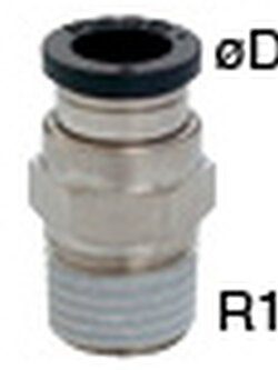

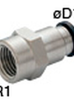


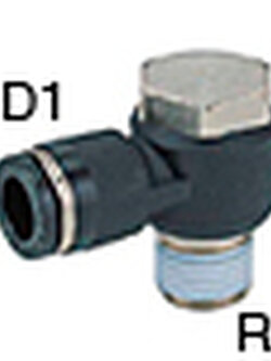
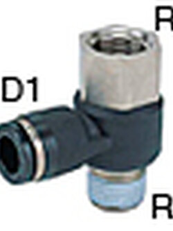

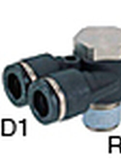
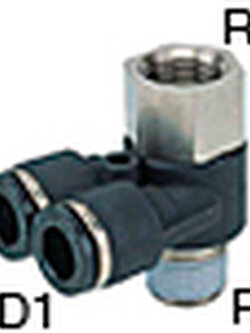
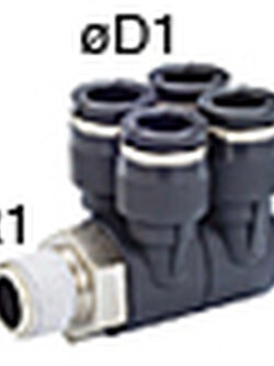

MEMBER ZONE
 บริษัท ไทเกอร์ เอ็นจิเนียริ่ง แอนด์ ซัพพลาย จำกัด
สมัครสมาชิกร้านนี้ เพื่อรับสิทธิพิเศษ
▲
▼
รายการสั่งซื้อของฉัน
รายการสั่งซื้อของฉัน
ข้อมูลร้านค้านี้

บริษัท ไทเกอร์ เอ็นจิเนียริ่ง แอนด์ ซัพพลาย จำกัด
จำหน่ายและนำเข้า อุปกรณ์โรงงานทุกชนิด LOCTITE FESTO CHELIC HIWIN REXON MITSUBISHI ABB YAZAKI TOYOX
เบอร์โทร : 0942595295
อีเมล : sj.2558ketmanee@gmail.com
อีเมล : sj.2558ketmanee@gmail.com
ส่งข้อความติดต่อร้าน
เกี่ยวกับร้านค้านี้
ค้นหาสินค้าในร้านนี้
ค้นหาสินค้า
สินค้าที่ดูล่าสุด
บันทึกเป็นร้านโปรด
Join เป็นสมาชิกร้าน
แชร์หน้านี้
แชร์หน้านี้
↑
TOP เลื่อนขึ้นบนสุด
TOP เลื่อนขึ้นบนสุด
สินค้าในตะกร้า ({{total_num}} รายการ)

ขออภัย ขณะนี้ยังไม่มีสินค้าในตะกร้า
ราคาสินค้าทั้งหมด
฿ {{price_format(total_price)}}
- ฿ {{price_format(discount.price)}}
ราคาสินค้าทั้งหมด
{{total_quantity}} ชิ้น
฿ {{price_format(after_product_price)}}
ราคาไม่รวมค่าจัดส่ง
➜ เลือกซื้อสินค้าเพิ่ม